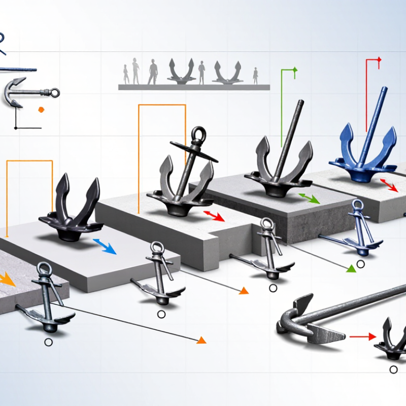
| Spherical-head anchor | A forged steel anchor is cast into the concrete. A compatible lifting clutch engages the anchor’s spherical head to transfer lifting force into the precast element. | Precast wall panels, beams, columns, and other concrete components lifted with a matching clutch system. | Anchor load class, embedment, concrete strength at lifting, edge distance, reinforcement, and the direction and angle of the lifting force. | Confirm that the clutch and anchor are a tested, compatible system. Check the design documentation for the actual load capacity and permitted loading directions. |
| Foot anchor | A steel anchor with an enlarged foot or end anchorage develops resistance by bearing against the surrounding concrete; reinforcement may be specified to support the load path. | Precast elements where the anchor geometry and reinforcement can be incorporated into the component design. | Foot dimensions, embedment depth, concrete cover, reinforcement arrangement, concrete strength, and risk of splitting or edge breakout. | Use the design for the specific element rather than selecting by anchor size alone. Verify lifting loads, including any sling-angle effects. |
| Pin anchor | A cast-in steel pin or pin-shaped anchorage transfers lifting force through its embedded portion and the surrounding concrete, often with a dedicated lifting attachment. | Precast components designed around a pin-type connection and its corresponding lifting hardware. | Pin geometry, embedment, concrete condition, attachment fit, load direction, and the required access for attaching and releasing the hardware. | Check the specified pin and lifting attachment combination, installation position, and inspection requirements before use. |
| Plate or spread anchor | An embedded plate or spread-shaped steel component distributes force into the concrete over a larger bearing area than a simple straight bar. | Precast units requiring a designed embedded plate arrangement or a lifting point integrated with reinforcement. | Plate geometry, weld and steel design where applicable, reinforcement detailing, concrete breakout resistance, and clearance from edges and openings. | Review approved shop drawings and lifting calculations. Do not substitute plate dimensions or reinforcement without engineering approval. |
| Loop anchor | A steel loop is embedded in the concrete, leaving a portion accessible for connection to a lifting hook or specified rigging hardware. | Precast products where an exposed loop is acceptable and the connection can be safely accessed during lifting. | Loop orientation, exposed length, steel and embedment details, concrete strength, rigging compatibility, and protection from damage or corrosion. | Confirm the intended connection method and whether the loop is designed for the planned load direction and reuse conditions. |
| Threaded lifting insert | A cast-in insert provides a threaded connection for a matching lifting eye or accessory, transferring load through the insert’s anchorage into the concrete. | Precast components using removable threaded lifting accessories or applications requiring a compact, flush connection point. | Thread size and condition, embedment, accessory engagement, concrete strength, edge distance, and the insert’s approved load directions. | Match thread form and size exactly. Inspect threads for debris, wear, or damage, and use only the specified lifting accessory. |
| Recess former with cast-in anchor | A temporary former creates a recess around a cast-in anchor. After stripping the former, a compatible clutch or lifting device can engage the anchor. | Precast units where the lifting point needs to sit within a formed recess for handling or finishing purposes. | Recess dimensions, anchor position, concrete cover, local reinforcement, access for clutch engagement, and recess condition after demoulding. | Check that the recess former does not interfere with reinforcement or reduce the designed concrete section around the anchor. |
| How a lifting-anchor system works | The anchor is positioned and secured in the mould, cast into the concrete, and connected to compatible lifting hardware after the concrete reaches the specified release strength. The crane load then passes through the hardware and anchor into the concrete and its reinforcement. | Factory handling, demoulding, transport, and erection of engineered precast concrete components. | Actual component weight, number and location of anchors, load sharing, sling angles, dynamic effects, concrete strength at each lift, and the full lifting sequence. | Follow the component-specific lifting plan. Anchor capacity is not the same as component lifting capacity; the concrete, reinforcement, rigging, and geometry must all be checked. |
| Global procurement and compliance checks | Anchor performance depends on the complete system and its installation, not on the metal component alone. | International sourcing for precast plants, infrastructure projects, and construction sites. | Applicable local regulations and project specifications; traceability; material and corrosion-protection requirements; installation instructions; and inspection or testing documentation. | Request technical data, declared load classes, compatible accessories, quality records, and language-appropriate instructions. Have a qualified engineer approve substitutions. |
| Important safety note | There is no universal safe working load for an anchor type. Use the capacity and installation limits stated for the specific engineered system, concrete element, and lifting configuration. Do not lift from damaged, incorrectly installed, or unverified anchors. |