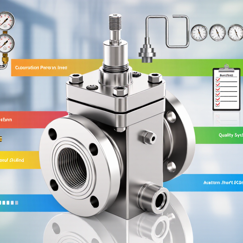
| Body Material | Carbon steel, stainless steel, duplex stainless steel, nickel alloys | Material selection depends on pressure, temperature, corrosion, fluid chemistry, and sour-service requirements. | Carbon steel for general industrial service; stainless or duplex grades for corrosive or chloride-containing media. | ASTM material specifications; ASME Section VIII; NACE MR0175/ISO 15156 where applicable. |
| Seal and Soft-Goods Material | PTFE, reinforced PTFE, graphite, elastomers, metal seals | Temperature and chemical compatibility vary significantly; graphite and metal seals are suited to higher-temperature service than many elastomers. | Select according to fluid compatibility, fugitive-emission requirements, fire exposure, and operating temperature. | Manufacturer material certificates; application-specific chemical compatibility review; ISO 15848 where fugitive emissions apply. |
| Block Configuration | Single-block, double-block, bypass-equipped, or multi-port manifold | Integrated passages reduce external joints and may simplify installation, isolation, inspection, and maintenance. | Single-block layouts for compact systems; double-block layouts where isolation and service continuity are important. | Project piping specifications; pressure-boundary design review; documented functional testing. |
| Valve Design | Needle, ball, poppet, piston, or check-valve arrangements | Needle valves provide fine adjustment; ball valves offer rapid quarter-turn isolation; check valves control reverse flow. | Use the configuration that matches flow control, shutoff, venting, backflow prevention, and maintenance requirements. | API 598 or applicable valve test procedures; project-specific pressure and seat-leakage criteria. |
| Pressure Rating | Instrument tubing ratings and ASME pressure-class connections | The allowable working pressure must be established at the actual design temperature and must not be based only on a nominal class or cold rating. | Choose a rating with adequate allowance for pressure, temperature, transients, vibration, and installation conditions. | ASME B16.5, ASME B16.34, or tubing-fitting specifications as applicable; pressure test records. |
| Connection Type | Threaded, tube fitting, socket-weld, butt-weld, and flanged connections | Connection choice affects installation time, leakage risk, inspectability, alignment, and suitability for vibration or high-temperature service. | Compression or tube connections for instrumentation; welded or flanged connections for higher-integrity process installations. | ASME B16.5, ASME B16.11, ASME B1.20.1, or applicable tubing-connection standards. |
| Relief-Valve Interface | Threaded, flanged, welded, or custom outlet/inlet interfaces | The interface must preserve the required flow area and avoid excessive pressure loss or undesirable discharge-side back pressure. | Use an integrated interface when compactness and reduced leakage points are priorities. | API 520 and API 521 for pressure-relief-system sizing and installation considerations. |
| Pressure-Relief Performance | Set pressure, blowdown, relieving capacity, and reseating behavior | Performance must be verified for the actual fluid, temperature, inlet pressure loss, outlet back pressure, and required relieving scenario. | Process vessels, piping systems, compressed-gas systems, and thermal-expansion protection. | API 520, API 526, API 527, ISO 4126, and ASME Section VIII, as applicable. |
| Leakage Control | Soft-seat, metal-seat, double-block isolation, and low-emission packing | Seat tightness and stem or body leakage should be tested using a defined procedure and acceptance criterion. | Critical hydrocarbons, toxic gases, vacuum service, and environmentally controlled facilities. | API 527 for pressure-relief-valve seat tightness; ISO 15848 for fugitive-emission classification where required. |
| Temperature Capability | Ambient, cryogenic, elevated-temperature, and fire-exposure designs | Material strength, seal elasticity, thermal expansion, and fluid phase behavior change with temperature. | Match the block and relief-valve assembly to the complete minimum and maximum design-temperature range. | ASME material allowable stresses; applicable cryogenic, fire-test, and pressure-relief requirements. |
| Corrosion and Sour-Service Suitability | Standard industrial service, chloride service, sour gas, and offshore service | Resistance depends on alloy chemistry, hardness, heat treatment, weld procedures, chloride exposure, and hydrogen-sulfide conditions. | Specify upgraded alloys and controlled manufacturing documentation for corrosive or sour environments. | NACE MR0175/ISO 15156 for oil and gas production sour service; NACE MR0103 where applicable to refining environments. |
| Testing and Documentation | Hydrostatic test, pneumatic test, seat-leakage test, functional test, and material traceability | A complete quality dossier may include certificates, test results, calibration records, drawings, and inspection reports. | Projects requiring inspection hold points, regulated equipment records, or long-term maintenance traceability. | ISO 9001 quality systems; applicable API, ASME, ISO, ASTM, and project inspection requirements. |
| Selection Priority for 2026 Projects | Safety compliance, material suitability, leakage prevention, maintainability, and lifecycle value | The best technical choice is determined by verified compliance and application fit rather than by nominal pressure rating alone. | Use a documented technical evaluation before purchase, especially for hazardous, corrosive, high-pressure, or high-temperature service. | Approved project specifications, applicable legal requirements, engineering calculations, and certified test documentation. |