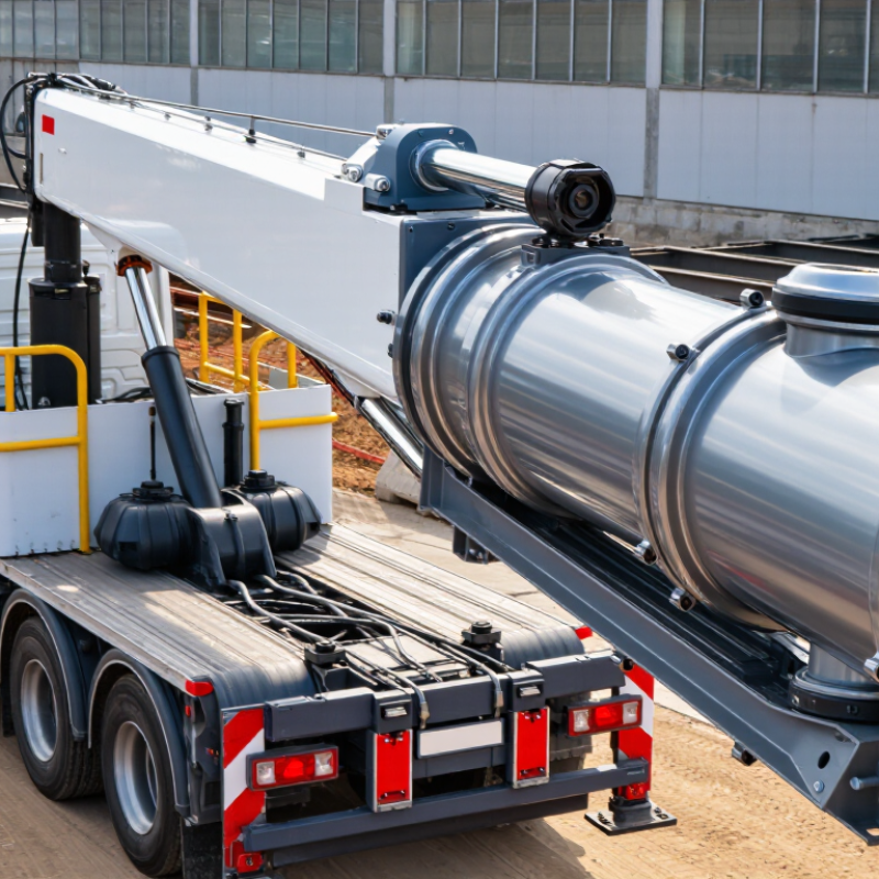
| Cylinder Type | Double-acting hydraulic cylinder for boom lifting, extension, or leveling functions. | Two pressurized chambers with a piston, rod, gland, and hydraulic ports sized for the crane circuit. | Provides controlled movement in both directions and supports positive load positioning. | Confirm whether the crane function requires holding, retraction force, or counterbalance-valve compatibility. | Essential |
| Bore Diameter | Select from the calculated force requirement; common truck-crane cylinders may use approximately 80–250 mm bores. | Honhed steel tube with a smooth internal surface and controlled dimensional tolerance. | A larger bore produces more force at the same hydraulic pressure but increases weight and oil volume. | Calculate force using: F = P × A. Allow for friction, geometry, dynamic loads, and a suitable safety margin. | Essential |
| Rod Diameter | Typically selected at approximately 50–70% of the bore diameter, subject to load and buckling analysis. | High-strength alloy steel with a hardened or induction-hardened surface. | Improves resistance to bending, column buckling, impact, and side loading. | Check extended length, unsupported length, eccentric loading, and minimum rod diameter against calculations. | Essential |
| Rod Surface | Hard-chrome-plated or alternative corrosion-resistant treated rod surface with consistent finish. | Ground and polished alloy steel; chrome thickness and substrate preparation should match the operating environment. | Reduces friction and wear at the rod seal while protecting against rust and scoring. | Inspect surface roughness, plating uniformity, pitting resistance, and compatibility with the selected seal. | High |
| Cylinder Tube | Precision-honed tube with a low-roughness internal bore and adequate wall thickness. | Cold-drawn or honed carbon/alloy steel tube designed for hydraulic pressure service. | Supports stable sealing, smooth piston travel, and reduced internal leakage. | Verify bore tolerance, roundness, straightness, pressure rating, and proof-test requirements. | Essential |
| Piston Material | Machined steel piston with wear-band grooves and a positive retention method. | Carbon or alloy steel, normally protected against corrosion where exposed to hydraulic fluid. | Maintains piston alignment and transfers hydraulic force efficiently. | Check piston-to-tube clearance, wear-band support, thread or nut retention, and resistance to extrusion. | High |
| Rod Seal | High-pressure polyurethane or reinforced PTFE seal selected for pressure, speed, and fluid type. | Single or multi-lip rod seal with an anti-extrusion element where pressure spikes are expected. | Limits external leakage and prevents dirt or moisture from entering around the rod. | Match seal temperature range, maximum pressure, rod speed, surface finish, and hydraulic-fluid compatibility. | Essential |
| Wiper Seal | Heavy-duty scraper/wiper designed for mud, dust, water, and road debris. | Polyurethane or equivalent elastomer with a firm outer scraping lip. | Protects the rod seal and reduces contamination-related wear during outdoor crane operation. | Check low-temperature flexibility, debris-scraping ability, retention in the gland, and resistance to pressure wash. | Essential |
| Piston Seal | High-pressure compact seal or PTFE-based seal suitable for the cylinder's pressure and speed range. | Polyurethane, PTFE compound, or other fluid-compatible material supported by a suitable backup ring. | Reduces internal bypass and helps the cylinder hold position under load. | Verify extrusion gap, pressure differential, piston speed, temperature, and fluid compatibility. | Essential |
| Wear Rings and Guide Bands | Non-metallic wear rings sized to carry side loads without allowing metal-to-metal contact. | Filled PTFE, phenolic composite, or other low-friction bearing material. | Improves alignment, protects the tube and piston, and extends seal service life. | Evaluate bearing pressure, side-load magnitude, guide width, thermal expansion, and replacement access. | High |
| Static Seals | O-rings and backup rings selected for hydraulic pressure, temperature, and fluid chemistry. | Nitrile rubber for common mineral oils; fluorocarbon elastomers for higher-temperature or specific-fluid service. | Prevents leakage at the gland, piston, ports, and end-cap joints. | Confirm elastomer compatibility, hardness, groove dimensions, squeeze, and extrusion protection. | Essential |
| Hydraulic Pressure | Design pressure commonly falls around 160–250 bar for many mobile hydraulic systems; confirm the actual circuit rating. | All pressure-bearing components should be rated above working pressure and tested appropriately. | Ensures adequate lifting force without excessive component stress. | Compare working, peak, relief-valve, and proof-test pressures; account for transient pressure spikes. | Essential |
| Stroke Length | Choose the shortest stroke that achieves the required crane geometry and mechanical travel. | Single-stage or multi-stage design depending on required reach and available installation space. | Controls lifting range, boom movement, installation envelope, and hydraulic oil consumption. | Allow clearance for end-of-stroke cushioning, hose routing, mounting-pin movement, and service access. | Essential |
| Operating Speed | Common hydraulic cylinder rod speeds are approximately 0.05–0.5 m/s, depending on flow and application. | Seal profile, port size, cushioning, and flow-control arrangement selected for the required speed. | Provides smooth boom movement and reduces shock loading at the end of travel. | Calculate speed from flow and effective area; check seal velocity limits and pressure losses. | High |
| Cushioning | Adjustable or fixed end-of-stroke cushioning where the moving mass can create impact. | Cushion sleeve, spear, needle adjustment, and bypass check arrangement integrated into the end cap. | Reduces impact, noise, pressure spikes, and structural stress at full extension or retraction. | Assess load mass, approach speed, oil viscosity, adjustment range, and maintenance accessibility. | High |
| Mounting and Side Load | Use spherical or self-aligning mounting arrangements where crane geometry creates angular movement. | Hardened pins, replaceable bushings, welded or bolted mounts, and alignment features. | Reduces bending loads on the rod and uneven wear on seals and guide bands. | Check pin shear, bearing stress, misalignment, mounting angle, and clearance through the complete stroke. | Essential |
| Corrosion Protection | Protection level selected according to road salt, rain, humidity, coastal exposure, and washing frequency. | Protective coating for the tube, corrosion-resistant rod treatment, plated hardware, and sealed gland features. | Extends service life and helps prevent rod pitting that can damage seals. | Specify coating system, salt-spray or environmental requirement, exposed-area protection, and touch-up procedure. | High |
| Hydraulic Fluid Compatibility | Confirm compatibility with the exact mineral-oil, biodegradable, fire-resistant, or synthetic fluid used. | Seal and backup-ring compounds selected by fluid chemistry and operating temperature. | Prevents swelling, shrinkage, hardening, softening, and premature seal failure. | Verify fluid type, viscosity range, additives, cleanliness level, and maximum continuous temperature. | Essential |
| Temperature Range | Typical mobile hydraulic service may range from approximately −20°C to +80°C, but the actual climate and fluid must be assessed. | Low-temperature-capable seals for cold starts and high-temperature compounds where heat buildup is significant. | Maintains sealing performance and material strength across seasonal operating conditions. | Check start-up temperature, continuous temperature, peak temperature, seal limits, and viscosity at cold start. | High |
| Load Holding and Safety | Use an appropriately rated counterbalance or load-holding valve close to the cylinder when required by the crane design. | Valve and cylinder combination designed to control runaway movement and hose-failure risk. | Improves load control during line failure, shock loading, or loss of hydraulic pressure. | Confirm valve setting, pilot ratio, response stability, hose-burst protection, and compliance with applicable regulations. | Critical |
| Pressure Testing | Perform controlled proof and leakage tests according to the applicable design standard and purchaser specification. | Documented test procedure covering pressure holding, external leakage, internal bypass, and functional movement. | Identifies manufacturing defects before installation and supports traceable quality control. | Request test pressure, duration, acceptance criteria, calibration records, and test documentation. | Critical |
| Maintenance and Serviceability | Choose a rebuildable design with accessible seals, replaceable wear rings, and available maintenance dimensions. | Threaded or bolted gland/end-cap construction with standard seal grooves and replaceable bushings. | Reduces downtime and allows economical seal replacement instead of complete cylinder replacement. | Check disassembly method, spare-seal identification, honing or rod-repair options, and inspection intervals. | High |
| Final Selection Rule | Select the cylinder only after confirming force, geometry, pressure, speed, side load, environment, and safety requirements together. | Application-specific design supported by hydraulic calculations and dimensional drawings. | Balances lifting capacity, reliability, weight, installation space, service life, and total operating cost. | Require a complete drawing, material and seal schedule, pressure rating, test record, and installation instructions. | Critical |