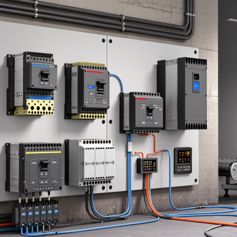
| Full-Voltage Non-Reversing Starter | Connects a three-phase or single-phase motor directly to the supply for one-direction operation. | Main contactor, thermal or electronic overload relay, control transformer or control power supply, start pushbutton, stop pushbutton, auxiliary holding contact, enclosure, and disconnecting means. | Momentary start command seals in the contactor through an auxiliary normally open contact. A stop command or loss of control power opens the contactor. | Overload trip opens the control circuit. Short-circuit protection is provided by an upstream fuse or circuit breaker. Undervoltage release prevents automatic restart after control power is lost. | Pumps, fans, conveyors, compressors, machine tools, and general-purpose motors with acceptable starting current. | Check motor full-load current, available fault current, starting frequency, enclosure rating, coil voltage, and the motor's permitted starting method. |
| Full-Voltage Reversing Starter | Runs a motor in forward or reverse by changing the phase sequence at the motor terminals. | Two mechanically linked contactors, overload relay, forward and reverse pushbuttons or selector switch, auxiliary contacts, control power supply, and reversing enclosure. | Forward or reverse contactor is energized by a maintained or momentary command. Electrical and mechanical interlocking prevents both contactors from closing simultaneously. | Includes overload protection, upstream short-circuit protection, electrical interlock, mechanical interlock, and commonly a stop or emergency-stop circuit. | Hoists, winches, conveyors, mixers, gates, positioning equipment, and machinery requiring bidirectional movement. | Allow the motor to stop before reversing unless the motor and driven load are specifically rated for plugging or dynamic braking. |
| Two-Speed Dahlander Starter | Provides two operating speeds from a motor with a consequent-pole winding arrangement. | Two-speed-compatible contactor arrangement, overload protection for each applicable operating condition, speed selector, auxiliary contacts, and control enclosure. | Low-speed and high-speed contactors are selected through an electrically interlocked control circuit. A break-before-make sequence is normally used. | Electrical and mechanical interlocking prevents incompatible winding connections. Overload settings must match the selected speed and motor data. | Fans, machine tools, pumps, and conveyors using a two-speed consequent-pole motor. | Use only with a compatible motor winding design. Confirm the motor connection diagram, speed ratio, acceleration time, and load torque at both speeds. |
| Two-Speed Separate-Winding Starter | Operates a motor with two independent stator windings at different rated speeds. | Separate contactor sets, overload relays or an appropriately configured electronic overload device, speed selector, auxiliary contacts, and control power supply. | The control circuit energizes one winding at a time and uses interlocking to prevent simultaneous operation unless the motor manufacturer permits it. | Each winding requires suitable overload protection. A timed transition or zero-speed changeover may be required to limit mechanical and electrical stress. | Industrial fans, machine tools, air-handling equipment, and applications requiring independent low- and high-speed ratings. | Verify the motor's separate-winding connection data, current ratings, acceleration requirements, and allowable switching sequence. |
| Wye-Delta Reduced-Voltage Starter | Reduces starting current by initially connecting a compatible motor in wye and then changing to delta for normal operation. | Line contactor, wye contactor, delta contactor, transition timer, overload relay, auxiliary contacts, and electrical and mechanical interlocking. | During starting, the wye contactor closes. After a preset time, the wye contactor opens and the delta contactor closes, usually with open transition. | The three contactors require interlocking to prevent a line-to-line fault. Overload placement and settings depend on the starter arrangement and motor current data. | Fans, pumps, compressors, and other loads with relatively low breakaway torque and motors designed for wye-delta starting. | The motor must have six accessible leads and be rated for delta operation at the supply voltage. Starting torque is lower than with full-voltage starting. |
| Autotransformer Reduced-Voltage Starter | Applies reduced voltage during starting and then connects the motor to full line voltage. | Autotransformer, starting contactor, running or bypass contactor, transition timer, overload relay, control circuit, and interlocking devices. | A timed sequence applies a selected transformer tap during acceleration, followed by transition to line operation through the running contactor. | Includes short-circuit protection, overload protection, contactor interlocking, transformer temperature considerations, and transition control. | Large motors driving pumps, fans, compressors, and conveyors where reduced line disturbance and higher starting torque are required. | Consider tap selection, motor starting torque, transformer duty, enclosure heat, transition type, and available short-circuit current. |
| Part-Winding Starter | Starts a motor by energizing part of a specially designed parallel winding first, then energizing the remaining winding section. | Starting contactor, secondary contactor, transition timer, overload relay, auxiliary contacts, and control power supply. | The first winding section is energized initially. After a timed delay, the second section is connected to complete the motor winding circuit. | The motor must be specifically designed for part-winding starting. Interlocking and correct timing help prevent improper energization and excessive current. | Selected refrigeration compressors, pumps, fans, and industrial motors equipped with part-winding leads. | Confirm the motor manufacturer's lead identification, starting current, transition time, and required contactor ratings before selection. |
| Electronic Soft Starter with Magnetic Bypass | Ramps motor voltage electronically to reduce inrush current and mechanical shock, then uses a contactor for efficient running when appropriate. | Silicon-controlled rectifier power section, bypass contactor, overload or motor-protection function, keypad or terminals, control power supply, and optional communications interface. | Voltage ramp, current limit, or torque-control parameters govern acceleration and deceleration. A bypass contactor may close after the ramp is complete. | May provide phase-loss, undercurrent, overcurrent, stall, electronic overload, and thermal model functions. Upstream short-circuit protection remains necessary. | Pumps, conveyors, compressors, fans, and high-inertia loads requiring controlled acceleration or reduced water hammer. | Check motor compatibility, bypass arrangement, ramp settings, number of starts per hour, heat dissipation, and whether deceleration control is required. |
| Across-the-Line Starter with Motor Protection Relay | Provides direct motor starting while adding adjustable electronic monitoring and protection. | Contactor, electronic motor-protection relay, current transformers or integrated current sensing, control terminals, auxiliary contacts, and enclosure. | Two-wire maintained control, three-wire momentary control, selector-switch control, or a programmable control input can operate the contactor. | Depending on the relay, functions may include overload, phase loss, phase reversal, current imbalance, locked rotor, underload, earth-fault indication, and thermal capacity monitoring. | Critical pumps, process equipment, packaged machinery, and motors requiring more diagnostic information than a basic thermal overload relay provides. | Set protection values from the motor nameplate and application data. Confirm sensor range, reset behavior, control voltage, and communication requirements. |
| Reversing Starter with Plugging or Braking Control | Reverses or stops a motor rapidly by controlled switching, plugging, or an added braking method. | Forward and reverse contactors, overload relay, speed-sensitive or time-based control, braking contactor or braking module where applicable, interlocks, and emergency-stop circuit. | Control logic supervises direction commands and may require a zero-speed signal, time delay, or anti-plugging timer before the opposite direction is enabled. | Requires careful protection against contactor overlap, excessive motor heating, repeated plugging, and unexpected restart. A separate braking resistor or brake controller may be used in some systems. | Material-handling systems, cranes, hoists, positioning machinery, and equipment requiring rapid stopping or directional changes. | Evaluate stopping energy, motor duty cycle, mechanical brake coordination, allowable reversals per hour, and the applicable machine-safety requirements. |