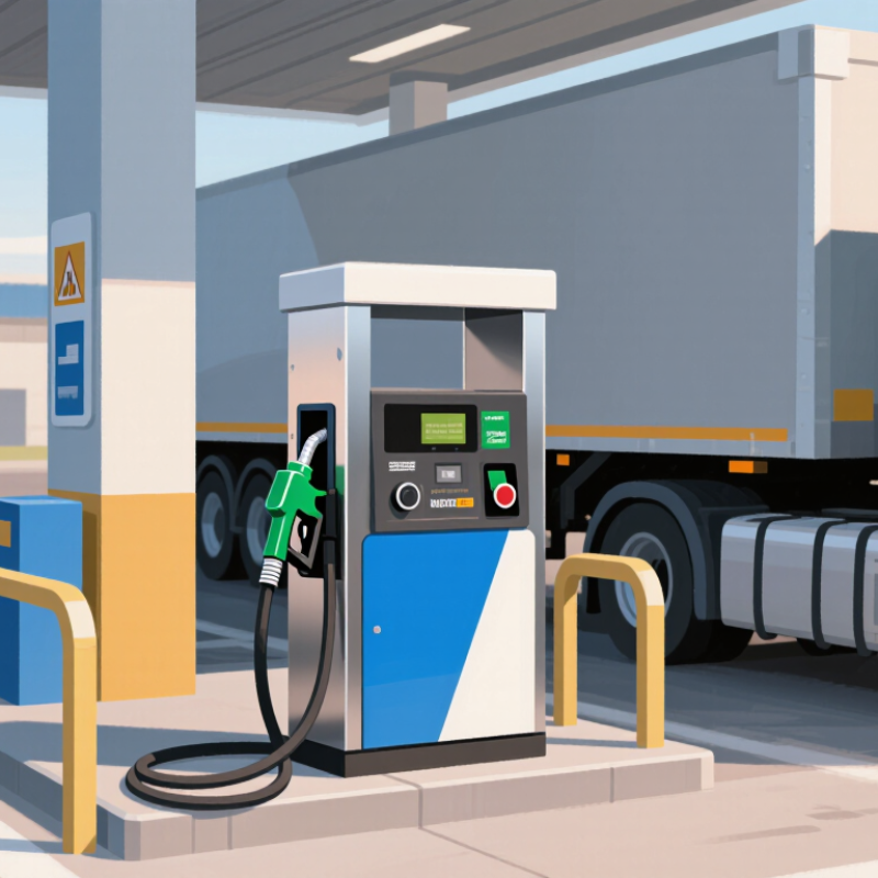
| Product flow path | One LNG product line delivers liquefied natural gas from the supply system to the vehicle through one dispensing hose. | Confirm that the flow schematic, operating sequence, and connection arrangement match the intended one-line, one-hose configuration. | Clear system boundaries help distinguish the LNG product path from any separate facility piping or auxiliary connections. |
| Fuel temperature and materials | LNG is cryogenic; its temperature is commonly near its atmospheric boiling point of about −162°C (−260°F), though actual conditions vary. | Verify that wetted components, seals, hose, fittings, and instrumentation are specified for the actual operating temperature and pressure range. | Materials and components must be suitable for cryogenic service to maintain safe, reliable containment. |
| Operating pressure | There is no single universal dispensing pressure for every LNG vehicle or station. | Check the dispenser’s rated pressure against the station design, vehicle requirements, and applicable codes; do not rely on a generic pressure figure. | Pressure compatibility affects safe connection, dispensing performance, and equipment selection. |
| Metering and transaction data | The dispenser measures the LNG delivered through its product line. | Review the metering method, stated measurement accuracy, calibration provisions, display units, and suitability for the intended commercial or fleet use. | Accurate, verifiable measurement supports dependable fuel accounting and transaction records. |
| Hose and vehicle connection | A single dispensing hose connects the dispenser to the vehicle’s LNG filling point. | Check connector compatibility, hose working limits, handling ergonomics, inspection requirements, and provisions for preventing unintended vehicle movement while connected. | A suitable connection and manageable hose reduce operating difficulty and help prevent connection-related hazards. |
| Emergency shutdown | The dispenser is integrated with the station’s emergency shutdown (ESD) arrangements. | Confirm how an emergency stop isolates or stops flow, where shutdown controls are located, and how the dispenser interfaces with the wider station system. | Shutdown functions need to work as part of the complete LNG installation, not just as an isolated dispenser feature. |
| Leak and release controls | The one-hose arrangement does not remove the need to manage potential LNG or vapor releases. | Assess connection integrity, appropriate isolation, inspection access, and the station’s procedures for detecting and responding to abnormal conditions. | Good release-control practices support safe operation and maintenance. |
| Standards and site compliance | Requirements depend on the installation location, application, and authority having jurisdiction. | Request the applicable design documentation, certifications, and evidence of conformity to relevant local regulations and recognized standards. | Compliance cannot be established from the dispenser configuration alone; the complete installation must be assessed. |
| Maintenance and support | A simpler flow arrangement still requires routine inspection and maintenance. | Compare service access, spare-parts availability, maintenance instructions, inspection intervals, and operator training requirements. | Maintainability affects operational availability and the ability to keep safety-critical components in serviceable condition. |
| Choosing the “best” option | “Best” depends on the vehicle interface, station design, throughput needs, operating environment, and local requirements. | Use a documented evaluation covering compatibility, safety functions, measurement needs, compliance, maintainability, and total operating requirements. | A feature-by-feature assessment is more reliable than choosing by configuration name alone. |