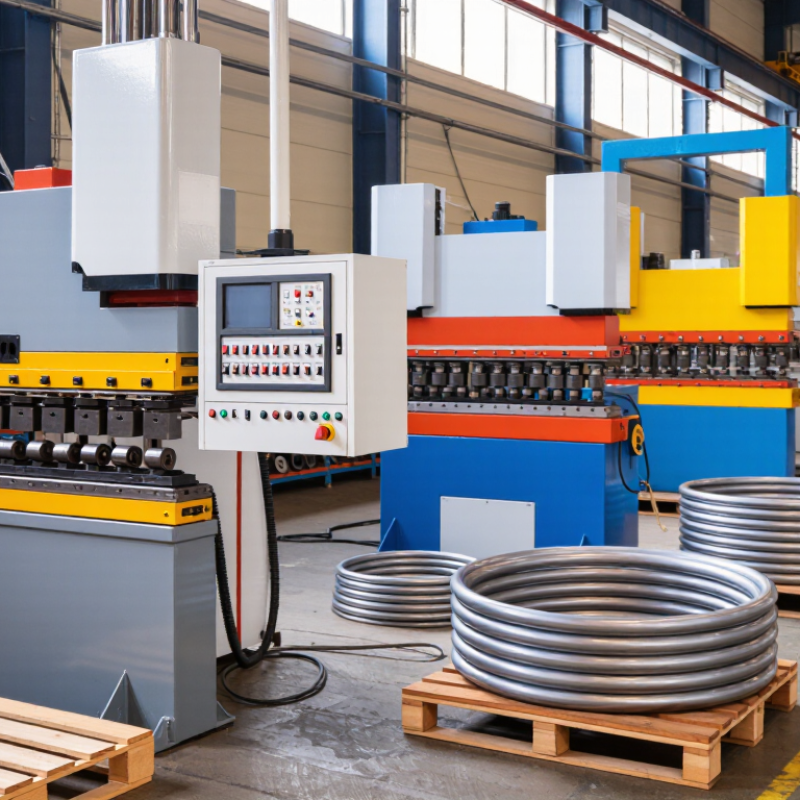
| Bending Principle | Three-roll ring bending | Suitable for circular and spiral forming; commonly used for medium and large pipe diameters. | Three powered or adjustable rolls apply progressive force while the pipe passes through the roll gap. The workpiece is gradually formed into a ring rather than bent in one stroke. | Offers continuous forming and good control of ring diameter. It is often selected when the required ring size is larger than the available die size. |
| Bending Principle | Rotary-draw bending | Uses a fixed-radius tooling set consisting of a bend die, clamp die, pressure die and often a mandrel. | The pipe is clamped to a rotating bend die and pulled around the die along a controlled centerline radius. | Provides accurate bend angles and repeatability. It is suitable for smaller rings, tight radii and applications where dimensional consistency is important. |
| Machine Configuration | Hydraulic pipe ring bender | Hydraulic cylinders provide the forming force; operating pressure and capacity depend on the machine design. | Hydraulic pressure moves rolls, dies or clamping components to deform the pipe progressively. | Delivers high forming force and is suitable for carbon steel, stainless steel and other heavy-wall tubing. Regular inspection of hoses, seals and hydraulic oil is required. |
| Machine Configuration | CNC-controlled ring bending machine | Programmable feed length, bending angle, roll position and forming sequence; some systems support recipe storage. | Servo or digitally controlled axes coordinate feeding, rotation and bending movements according to a programmed profile. | Recommended for repeated production, multi-step profiles and applications requiring reduced operator variation. |
| Workpiece Range | Round pipe and tube | Common production ranges extend from small tubing to large structural pipe, depending on roll size, motor power and wall thickness. | The rolls or tooling contact the outside diameter and apply bending moments until the material reaches the target curvature. | Confirm outside diameter, wall thickness, material grade, minimum bend radius and target ring diameter before choosing a machine. |
| Workpiece Range | Square and rectangular tube | Requires compatible rolls, guides and tooling; corner deformation can be greater than with round pipe. | The section is supported and progressively formed while the tooling controls the orientation of the profile. | Useful for frames, architectural structures and guardrails. Internal support or special tooling may be needed to limit flattening and corner distortion. |
| Material Compatibility | Carbon steel | Generally offers good formability and is widely processed on standard heavy-duty equipment. | The material is plastically deformed beyond its elastic limit while the rolls or die maintain the required curvature. | Springback should be considered, especially with high-strength grades. Test bending is recommended when the material specification changes. |
| Material Compatibility | Stainless steel and aluminum | Can be processed with suitable tooling, surface protection and force settings. | The machine applies controlled forming pressure while reducing surface scratching and excessive localized deformation. | Use clean tooling and appropriate lubrication where permitted. Aluminum usually requires careful control because it is more sensitive to surface damage and cracking. |
| Dimensional Control | Springback compensation | Actual compensation depends on material strength, temper, wall thickness, bend radius and forming method. | After load removal, the pipe partially returns toward its original shape. The machine therefore bends slightly beyond the nominal target. | Compensation is normally established through trial pieces, measurement and stored production settings rather than by relying on one universal value. |
| Quality Indicators | Ovality and wall-thickness change | Control limits should be defined by the drawing, applicable standard or customer specification. | Material flows during bending; the outside of the bend tends to stretch, while the inside tends to compress. | Use proper support, suitable tooling and gradual forming to reduce flattening, wrinkling and excessive thinning. |
| Production Efficiency | Automatic feeding and positioning | May include powered feeding, length stops, encoders and programmable positioning. | The system feeds the pipe to a defined position and coordinates the next bending operation without repeated manual measurement. | Improves cycle consistency and reduces setup time in batch production. It is less critical for occasional, low-volume work. |
| Tooling | Interchangeable rolls and dies | Tool dimensions must match pipe outside diameter, profile geometry and target radius. | Tooling transfers force to the correct contact points and guides the pipe during forming. | Ask for tooling changeover time, available diameter ranges and replacement-part availability when comparing machine configurations. |
| Safety | Guarding and emergency stop system | Important features include guards around pinch points, emergency-stop controls and clearly defined operating procedures. | Safety systems limit access to moving rolls, rotating tooling and the pipe path during machine operation. | Operators should receive training and keep hands, clothing and tools away from pinch points. Lockout procedures are required during maintenance. |
| Inspection | Dimensional verification | Typical checks include ring diameter, bend angle, ovality, end alignment and visible surface condition. | Measurements are compared with the engineering drawing or production tolerance after forming and, when necessary, after springback stabilization. | Calipers, templates, radius gauges, height gauges or coordinate measurement equipment may be selected according to the required accuracy. |
| Selection Criteria | Capacity matching | Machine selection should be based on maximum outside diameter, wall thickness, material strength, minimum radius and ring size. | The required forming moment is determined by the pipe section and material resistance, while the tooling determines achievable geometry. | Published capacity ranges are not universal. Compare the complete technical specification and request a sample bend using the actual pipe material. |