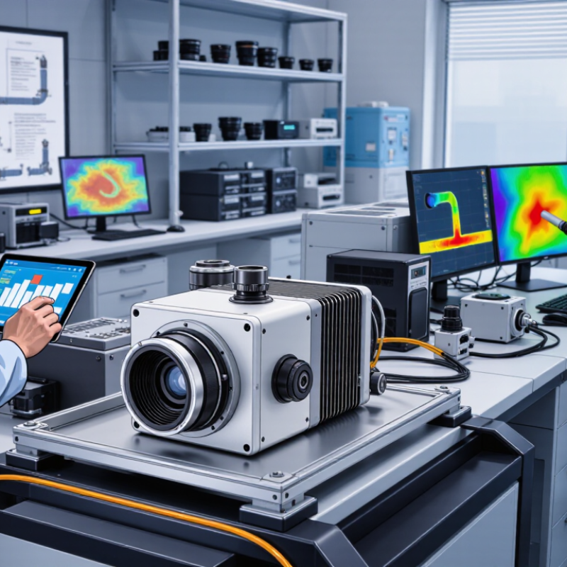
| Definition | Infrared camera module with a cooled detector and integrated electronics | The detector is actively cooled to reduce thermal noise and improve sensitivity. | Choose a cooled module when very small temperature differences, long-wave sensitivity, or high-speed measurement is essential. |
| Operating Principle | Infrared radiation → optical focusing → photon detection → signal processing → digital image output | The detector converts infrared energy into electrical signals that are corrected and displayed as an image or measurement. | Confirm that the module provides the required output interface, calibration functions, and software support. |
| Detector Material | Common cooled photon-detector materials include InSb, MCT/HgCdTe, and other compound semiconductor detectors. | Detector material affects spectral response, sensitivity, cooling requirement, and application suitability. | Match the detector material to the target wavelength band and measurement environment. |
| Spectral Band | Typical options include SWIR: approximately 0.9–2.5 µm; MWIR: approximately 3–5 µm; LWIR: approximately 8–12 µm. | The spectral band determines which infrared wavelengths the camera can detect efficiently. | Select the band according to target temperature, material emission, atmospheric transmission, and any required spectral signatures. |
| Cooling Method | Closed-cycle mechanical coolers, commonly based on Stirling-cycle technology | The cooler lowers detector temperature and helps suppress dark current and other noise sources. | Evaluate cooler vibration, warm-up time, operating life, acoustic noise, and maintenance requirements. |
| Detector Temperature | Often approximately 60–120 K, depending on detector type and design | Lower detector temperatures can reduce thermal noise, but they generally increase system complexity and power demand. | Check the stabilized operating temperature, cool-down time, and temperature-control accuracy. |
| Array Resolution | Common formats range from 320 × 256 and 640 × 512 to larger scientific formats. | Resolution determines the number of spatial sampling points in each image. | Choose resolution together with lens focal length, target distance, and the minimum object size to be measured. |
| Pixel Pitch | Common cooled detector pixel pitches include approximately 10–30 µm, depending on the detector family. | Pixel pitch influences spatial sampling, optical design, detector size, and achievable field of view. | Ensure the lens and detector are matched; a smaller pixel pitch does not automatically guarantee better measurement accuracy. |
| Thermal Sensitivity | High-performance cooled systems may achieve NETD values below 20 mK under specified test conditions. | NETD represents the smallest temperature difference that can be distinguished under defined conditions; lower values indicate better sensitivity. | Compare NETD using the same integration time, frame rate, spectral band, optics, and measurement method. |
| Frame Rate | Application-dependent; tens to hundreds of frames per second are common in high-speed configurations. | Frame rate defines how quickly the camera captures sequential images. | For high-speed events, verify the full-resolution frame rate, exposure time, data-transfer bandwidth, and windowing modes. |
| Integration Time | Short integration times are used for fast motion; longer integration times can improve signal collection in low-light infrared conditions. | Integration time is the period during which the detector collects infrared signal. | Select a module with an adjustable range suitable for both the target speed and expected radiation level. |
| Dynamic Range | Often specified by detector bit depth and usable signal range; 12-bit, 14-bit, and 16-bit data formats are widely used. | Dynamic range describes the ability to capture weak and strong signals without excessive saturation or quantization loss. | Use higher dynamic range for scenes containing both low-contrast and high-radiance objects. |
| Temperature Measurement | Radiometric measurement requires calibration, emissivity settings, reflected-temperature compensation, and appropriate optics. | A cooled camera can provide highly sensitive radiometric data, but accuracy depends on more than detector sensitivity alone. | Confirm radiometric output, calibration traceability, temperature range, and the stated accuracy under defined conditions. |
| Optical Interface | Fixed, interchangeable, or application-specific infrared lenses; field of view depends on focal length and detector format. | The optical system determines how much of the scene is observed and how large the target appears on the detector. | Calculate instantaneous field of view and ensure the target occupies enough pixels for reliable detection or measurement. |
| Output Interface | Common interfaces include Camera Link, GigE Vision, USB, CoaXPress, and vendor-neutral digital protocols. | The interface controls data bandwidth, cable length, integration effort, and compatibility with acquisition systems. | Match interface bandwidth and protocol support to the required resolution, frame rate, and recording system. |
| Power and Cooling Requirements | Higher than uncooled modules because the system must operate a cooler and temperature-control electronics. | Power consumption and heat dissipation can affect enclosure design, portability, and continuous operation. | Check input voltage, peak power during cool-down, steady-state power, thermal management, and available installation space. |
| Stabilization and Calibration | Typical functions include non-uniformity correction, bad-pixel replacement, gain adjustment, and temperature stabilization. | These functions improve image consistency and reduce pixel-to-pixel response variation. | Verify correction methods, calibration frequency, shutter or shutterless operation, and performance after warm-up. |
| Typical Applications | Scientific research, spectroscopy, semiconductor inspection, combustion analysis, astronomy, defense imaging, and high-speed thermal testing. | These applications benefit from high sensitivity, spectral selectivity, low noise, or fast imaging. | Define the main application before choosing detector band, resolution, frame rate, cooling level, and interface. |
| Cooled vs. Uncooled Choice | Cooled: higher sensitivity, faster response, and broader specialized-band options; Uncooled: lower cost, lower power, and simpler operation. | Cooling improves detector performance but adds size, power use, warm-up time, vibration, and system cost. | Choose cooled technology only when its performance benefits justify the additional system complexity. |
| 2026 Selection Checklist | Band, detector type, resolution, pixel pitch, NETD, frame rate, integration time, interface, power, cooling, calibration, and software | A balanced specification review prevents a high-performance feature from creating a bottleneck elsewhere in the system. | Request complete test conditions and evaluate the module using a representative target, lens, acquisition computer, and operating environment. |