How to Choose a Strain Wave Gear for Your Application
Choosing a strain wave gear begins with the job it must perform, not the smallest package in a catalog. A compact housing may fit neatly beside a robot joint, yet still struggle with peak torque, shock loads, or repeated reversals. C. Walton Musser, who introduced strain-wave gearing, remains a foundational figure in this field. A careful paraphrase of his design insight is: “High reduction in a compact mechanism still depends on understanding how its elements deform and share load.” That distinction matters. A strain wave gear uses controlled elastic deformation; it is not simply a conventional gearbox made smaller.
This guide explains how to match gear ratio, rated torque, stiffness, backlash, and service life to real operating conditions. Start with the motor speed and required output speed. Then check acceleration, duty cycle, mounting orientation, and the space available for bearings and seals. A gear that performs well in a clean laboratory may face dust, heat, vibration, or frequent direction changes in production. Small details count. A cable routed too close to the housing can complicate assembly.
Specifications help, but they do not replace application judgment. Peak torque figures, for example, may describe brief events rather than continuous operation. Ask the supplier how ratings were measured, and compare assumptions carefully. One uncomfortable truth: early estimates are often incomplete. Revisit them after testing. The sections ahead offer a practical framework for selecting a strain wave gear, spotting trade-offs, and confirming that the chosen unit suits the machine—not just the spreadsheet.
Understanding Strain Wave Gear Design and Operating Principles
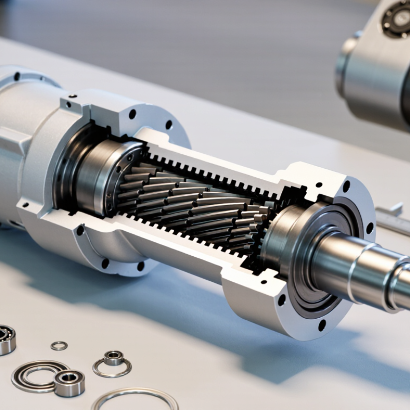
A strain wave gear converts high-speed input into slow, precise output through controlled elastic deformation. Its main parts are a wave generator, a flexible toothed cup called the flexspline, and a rigid circular spline. The wave generator uses an oval cam and bearing to press the flexspline outward at two opposite zones. Teeth engage in those zones, while the difference in tooth counts creates reduction as the generator turns.
Small motions matter.
This design can provide a large reduction ratio in a compact assembly, often with very little backlash. The ratio depends on the tooth-count difference, not just the gear’s outside diameter. A higher ratio may suit a robot joint that needs slow, measured movement, but it does not automatically mean better performance. Output torque, torsional stiffness, speed, and allowable moment loads also matter. A catalog torque figure is only a starting point; repeated reversals or shock loads can change what works in practice.
Check the duty cycle, mounting space, shaft alignment, and expected operating temperature before choosing a size. Friction and flexing generate heat, so lubrication and cooling conditions deserve attention, especially during long runs. Also ask whether the application needs positioning accuracy or sustained load capacity; these demands can pull the selection in different directions. Test the gear with a representative load if possible. Paper specifications help, but real motion can expose a mismatch.
Defining the Application’s Motion and Load Requirements
Define the motion before comparing gear ratios. Record the required output speed, travel angle, acceleration, deceleration, and reversal frequency. Then calculate continuous and peak torque separately; short acceleration spikes can exceed the steady load. Include the payload’s inertia and distance from the axis. A small arm carrying a tool at full extension may demand more torque than its mass suggests. The International Federation of Robotics’ World Robotics 2024 report counted 541,302 industrial robot installations in 2023, underscoring how many automated joints depend on correctly sized motion components. That figure is industry context, not a gearbox-sizing rule.
Check the full duty cycle, not just the maximum load. Note how long the gear runs, how often it starts and stops, and whether impacts or external radial and axial forces reach the output. Compare these demands with the gear’s rated torque, allowable moment load, torsional stiffness, and backlash. Also check the operating temperature and lubrication conditions. A neat spreadsheet can still miss an occasional jam or an unusually heavy end-of-arm tool. Measure where possible.
Tips: Log motion and load during a representative work cycle. Keep a margin for uncertain peaks, but avoid oversizing without reason; added inertia can raise acceleration demands. Recheck the selection after prototype testing.
Matching Gear Ratio, Torque, Speed, and Precision
Choose the gear ratio from the required output speed, not from torque alone. A higher ratio reduces output speed and can increase available torque, but it does not remove motor limits or losses. Check the motor’s operating speed and the gear’s input-speed rating together. Then compare required torque with both continuous and peak ratings. A brief acceleration spike is not the same as a load held throughout a shift. Heat matters. Duty cycle, starts per hour, and load inertia all affect what the gear can handle in practice.
Precision needs more than a low backlash figure. Check lost motion, repeatability, and torsional stiffness against the movement your application actually requires. A robot joint that reverses direction often may reveal compliance that a slow positioning test misses. Mounting accuracy matters, too; poor alignment can add friction and shorten service life.
I would leave a margin rather than select a gear that only meets the nominal numbers. Still, there is no single safe margin for every machine. A spreadsheet can make the choice look cleaner than it is. Test the proposed gear under representative loads, speeds, and operating cycles before finalizing the design.
Checking Size, Mounting, Materials, and Environmental Limits
Choosing a strain wave gear starts with the load, speed, and available space. Check peak torque as well as continuous torque; short acceleration bursts can exceed a unit’s rating. Compare the required reduction ratio with the motor’s operating range. Leave room for cables, fasteners, and service access. A compact drawing can reveal a clearance problem early.
Mounting details matter. Confirm the shaft dimensions, pilot fit, bolt pattern, and allowable installation orientation against the manufacturer’s technical data. The gear housing should sit on a sufficiently stiff surface. A flexible bracket may twist under load and affect positioning accuracy. Tighten fasteners in a controlled sequence, and avoid pulling misaligned parts together with bolts. Small errors here are easy to miss.
Material and environmental limits deserve equal attention. Check housing and bearing materials, lubricant compatibility, and corrosion protection for the actual workplace. Dust, washdown, temperature swings, and vibration can change service needs. Seals are not magic. Verify ingress limits rather than assuming protection from appearance. The catalog calculation is only a starting point; real duty cycles can be messy. I would review the load profile and mounting stiffness before final selection, then confirm the choice with application-specific data.
How to Choose a Strain Wave Gear: Ratio and Output Speed
Illustrative output speeds for representative reduction ratios, calculated from a constant 3,000 rpm input. Use this as an initial speed check; confirm rated torque, dimensions, mounting interfaces, materials, and environmental limits against the specific gear’s technical data.
Selection note: Higher reduction ratios produce lower output speed at the same input speed. Before choosing a unit, check that its size and mounting pattern fit the installation, its materials suit the load and surroundings, and its rated limits cover temperature, contamination, and other environmental conditions.
Evaluating Performance Data and Confirming Gear Compatibility
A strain wave gear can look suitable on a catalog page and still miss the needs of a real joint. Compare rated and peak torque, torsional stiffness, lost motion, efficiency, and service life under the same speed, load, and temperature conditions. A single efficiency figure is not enough. Check how the supplier measured it. The International Federation of Robotics reported 4,281,585 industrial robots operating worldwide in 2023, up 10% from 2022 (World Robotics 2024). That growing installed base makes reliable joint performance a practical design concern, not just a catalog detail.
Confirm the mechanical interface before comparing models. Match the input and output mounting faces, shaft or hollow-bore dimensions, fasteners, and allowable load at the output bearing. Then check whether the gear can handle the application’s peak acceleration, reversing loads, and duty cycle. Small details matter. A motor’s inertia and the gear’s permitted misalignment can affect performance, even when the torque rating appears adequate. If test conditions are missing, treat the quoted life or efficiency as uncertain and request the underlying method.
Tips: Build a simple comparison sheet with load, speed, temperature, duty cycle, and mounting dimensions. Ask for performance curves across your operating range, not just a nominal point. Test a sample under representative loads; laboratory conditions may not reflect your machine.