Request Quote

Request a quote from Nidec Drive Technology America Corporation.

This quote form is intended for customers and partners in North America seeking information about Nidec Drive Technology America Corporation’s Precision Gearing Technologies. For inquiries related to the Nidec motor group division or from outside this region, please visit the global Nidec Group website to find the appropriate regional or product-specific contact.

Subscribe to Nidec Newsletter

Subscribe to our email newsletter to stay current with our precision gearing solutions, featured products, company updates, and industry news.

How to Choose Pneumatic Valves for Industrial Applications?

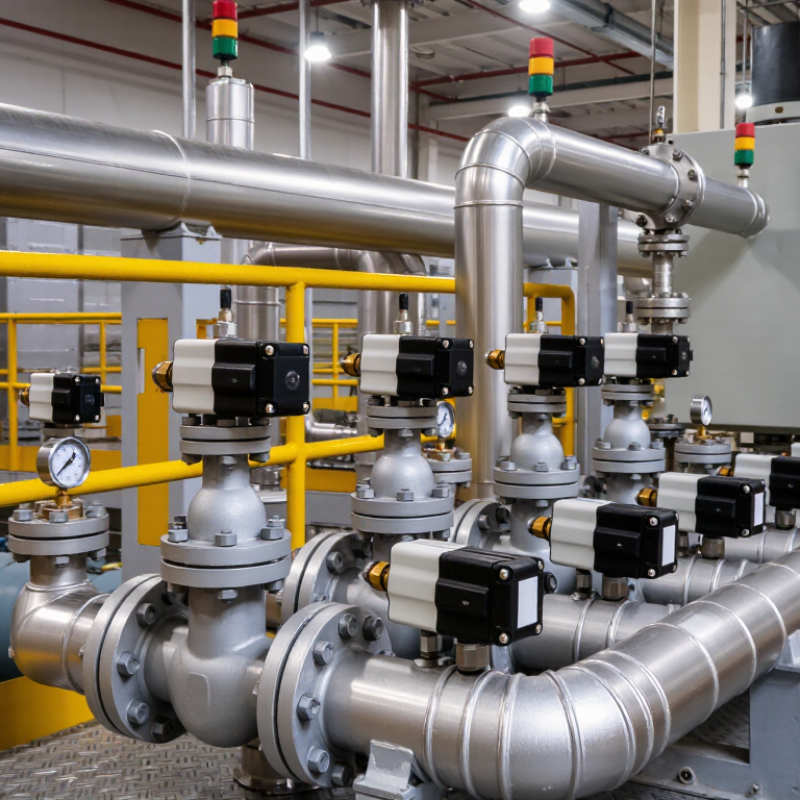
Pneumatic Valves control compressed air, yet choosing them is rarely a simple catalog exercise. In a factory, a valve may cycle thousands of times daily beside heat, oil mist, vibration, and dust. The wrong choice can create slow actuators, air leakage, noisy operation, or unexpected downtime. This guide explains how to match valve function, port size, pressure range, flow capacity, actuation method, and environmental protection to the real machine.

Start with the application, not the brand. Identify whether the circuit needs directional control, pressure regulation, flow adjustment, or isolation. Check the actuator’s bore, stroke, required speed, and available air pressure. A compact cylinder might work well with a small solenoid valve, while a large press may require higher flow and a carefully sized exhaust path. Consider response time, duty cycle, electrical voltage, connector protection, and maintenance access. In washdown areas, suitable enclosure ratings and corrosion-resistant materials matter. In dusty plants, contamination control deserves equal attention.

Standards and manufacturer data should support every selection. Confirm operating limits using published technical specifications, not assumptions from similar equipment. Experience also teaches a less comfortable lesson: oversizing is not always safer. It can increase cost, exhaust noise, and control difficulty. Undersizing is worse, but both choices deserve testing. Review the circuit with maintenance technicians, simulate likely failure modes, and test the valve under actual load conditions. A reliable selection balances performance, service life, safety, energy use, and future replacement availability.

How to Choose Pneumatic Valves for Industrial Applications?

Define the Role of Pneumatic Valves in Industrial Systems

How to Choose Pneumatic Valves for Industrial Applications?

Pneumatic valves define how compressed air moves through an industrial system. They start, stop, direct, and regulate airflow. This role affects machine speed, positioning accuracy, and operator safety. A directional valve, for example, controls a cylinder’s extension and return. A pressure-control valve protects actuators from unstable supply pressure. A flow-control valve adjusts motion near a conveyor stop or filling station.

The U.S. Department of Energy reports that compressed air can consume 10–15% of industrial electricity. It also identifies leaks as a major source of avoidable waste. Therefore, valve selection involves more than port size. Engineers should check pressure range, flow capacity, response time, sealing material, and the required failure position. On a dusty production floor, contamination can damage a poorly protected valve. In wet areas, corrosion resistance becomes essential. A larger valve is not automatically better. Oversizing may increase air consumption and reduce control quality. I would still verify real cycle data, because catalog values rarely reflect every installation.

Tips: Match the valve’s flow coefficient to the actuator demand. Test the complete circuit under normal load. Record pressure drops at the machine, not only at the compressor. Review emergency-stop behavior and choose a safe default position. Small details matter. But maintenance access is often overlooked. A valve hidden behind guarding may cost more downtime than its purchase price. According to the International Energy Agency, industrial efficiency depends heavily on reducing avoidable energy losses, making practical monitoring a necessary part of valve selection.

Match Valve Types to Actuation and Control Requirements

Choosing a pneumatic valve starts with the actuator, not the catalog. A single-acting cylinder usually needs a 3/2 valve with spring return. A double-acting cylinder generally needs a 5/2 valve. Use a 5/3 valve when the cylinder must stop, float, or hold pressure between strokes. Check the required flow rate, operating pressure, cycle speed, and port size together. A valve that fits mechanically may still cause slow motion and unstable positioning.

Control logic matters just as much. Solenoid actuation suits frequent, repeatable switching through a PLC. Manual or mechanical actuation can be more dependable near simple guarding or low-cycle equipment. For delicate gripping, dosing, or pressing, proportional valves offer finer control than basic on/off designs. Define the safe state before selecting the spring position. On air loss, should the actuator retract, extend, or remain locked? ISO 8573-1 air-quality classes also matter, because water and particles can damage small valve clearances.

Tips: Measure actual cycle time at the machine, not only on the drawing. The U.S. Department of Energy reports that compressed air can consume 10–15% of industrial electricity, while leaks may waste 20–30% of compressor output. Oversized valves can increase consumption without improving control. I have seen selection decisions focus on maximum flow alone. That is an incomplete test. Recheck exhaust speed, muffler restriction, tubing length, and emergency behavior. A smaller valve may work better, but only after real load testing.

Evaluate Pressure, Flow, Port Size, and Media Compatibility

Selecting a pneumatic valve starts with the machine’s real operating conditions, not the catalog headline. Check minimum and maximum pressure, then include pressure loss through tubing, fittings, and filters. A valve rated for 8 bar may perform poorly when supply pressure falls during peak demand. The U.S. Department of Energy’s Improving Compressed Air System Performance sourcebook reports that leaks can waste 20–30% of compressor output. Poor valve sizing can add another hidden cost through unnecessary pressure drop.

Flow capacity must match cylinder speed and required force. Compare the valve’s Cv or flow rating under the same pressure conditions. Port size matters, but a larger port does not automatically deliver better performance. A short 6 mm tube may restrict flow more than a carefully selected valve. In field testing, I would measure cycle time at the actuator, not trust calculated figures alone. The result can be humbling.

Tips: Record peak flow, working pressure, port thread, and ambient temperature before ordering. Confirm whether the media is dry air, lubricated air, nitrogen, water, or another gas. ISO 8573-1 classifies compressed-air purity by particles, water, and oil; that detail affects seals and valve materials. Chemical compatibility tables are useful, but they are not perfect. Temperature, concentration, and exposure time can change material behavior. Leave a small performance margin, then validate it under actual load.

How to Choose Pneumatic Valves for Industrial Applications?

Evaluate pressure, flow, port size, and media compatibility before selecting a valve.

The chart shows representative screening values for common pneumatic actuator sizes. Most industrial pneumatic systems operate near 6 bar, while required flow increases with actuator size. Select a port size that can deliver the required flow without excessive pressure loss.

Selection Factor Practical Reference
Pressure Confirm that the valve rating exceeds the system pressure. Typical compressed-air equipment operates around 5–8 bar.
Flow Compare the valve flow coefficient or rated flow with the actuator demand to achieve the required response time.
Port Size Common nominal connections include G1/8, G1/4, and G1/2. Larger actuators generally require larger ports and tubing.
Media Compatibility Clean, dry compressed air is the normal medium. Inert gases may require suitable seals, while oxygen and chemically aggressive media require dedicated material compatibility and safety approval.

Select Materials, Seals, and Environmental Protection Features

How to Choose Pneumatic Valves for Industrial Applications?

Material selection should match the working environment, not just the purchase price. Aluminum valve bodies suit clean, dry facilities and reduce weight. Stainless steel performs better near washdown areas, salt, chemicals, or high humidity. However, stainless steel does not solve every corrosion problem. Thread materials, fittings, and mounting hardware also need protection. I once saw rust develop around untreated fasteners while the valve body remained clean.

Seals require equal attention. Nitrile rubber works well with standard compressed air and moderate temperatures. Fluorocarbon seals handle higher heat and many oils, but compatibility must be checked against every fluid. EPDM can suit hot water and some chemicals, yet it may fail when exposed to certain oils. Always compare the seal’s temperature range, pressure rating, and expected service life. A seal that survives in testing may still wear quickly under frequent cycling.

Tips: Inspect the air supply first. Moisture, dust, and compressor oil can shorten valve life. Use filtration, drainage, and suitable protection when needed. In dusty or wet areas, select an enclosure with an appropriate IP rating. Remember, the rating usually describes the enclosure, not every internal component. This detail is easy to miss. Review maintenance access, too. A highly protected valve becomes impractical if technicians cannot inspect or replace its seals safely.

Verify Installation, Maintenance, Safety, and Total Operating Cost

Choosing pneumatic valves for industrial applications requires more than matching port size and operating pressure. Verify the installation conditions before approving a valve. Check air quality, ambient temperature, actuator force, tubing length, and mounting direction. A valve that performs well on a test bench may respond slowly beside a vibrating compressor. Confirm pressure ratings against real operating peaks, not only the average reading. Leave access for inspection and manual override.

Maintenance requirements also affect the correct choice. Select a design with visible indicators, replaceable seals, and clear service instructions. Drain moisture from the air system and inspect fittings for small leaks. Small leaks become expensive. A documented maintenance schedule improves reliability, but it should reflect actual cycling frequency. A low-cycle valve may fail early in a dusty, high-cycle environment.

Safety must remain practical. Use suitable exhaust control, guarded moving parts, and a dependable emergency shutoff arrangement. Confirm that the valve reaches a safe position after air loss. Ask technicians to test this condition during commissioning. They may notice hazards that a specification sheet misses. Total operating cost includes purchase price, compressed-air consumption, downtime, spare parts, labor, and disposal. A cheaper valve can demand more energy through internal leakage. That calculation is easy to overlook. Review performance records after installation, because assumptions sometimes fail in real production.

How to Choose Pneumatic Valves for Industrial Applications? - Verify Installation, Maintenance, Safety, and Total Operating Cost

Use this practical selection table to compare pneumatic valve options and verify the conditions that most strongly influence reliability, safety, compressed-air consumption, and total operating cost.

Evaluation Area Selection Criterion Recommended Practice and Typical Data Verification Method Operating-Cost or Safety Impact
Application Requirements Valve function Select directional control according to the actuator and process requirement: 3/2-way for single-acting actuators and 5/2-way for double-acting actuators. Use 5/3-way when an intermediate actuator position is required. Confirm the actuator type, required fail position, number of ports, and switching logic against the pneumatic schematic. Incorrect function can cause unexpected motion, production stoppage, or unsafe loss of control.
Flow capacity Size the valve using the required flow rate and response time. Common industrial directional valves are often specified from approximately 300 to 3,000 Nl/min, depending on port size and design. Compare the valve flow coefficient or rated flow with actuator volume, stroke time, tubing length, and working pressure. An undersized valve increases cycle time and pressure loss; an oversized valve may increase purchase cost and exhaust noise.
Working pressure Match the valve's operating range to the system pressure. Many general industrial systems operate near 5 to 7 bar(g); verify the minimum and maximum pressure stated for the selected valve. Check the pressure regulator setting, compressor pressure, pressure fluctuations, and the valve nameplate or technical datasheet. Pressure outside the rated range can cause incomplete switching, leakage, seal damage, or shortened service life.
Medium and air quality Use clean, dry, filtered compressed air. A common preparation level is filtration at approximately 5 µm; use finer filtration when required by the valve or process. Inspect the filter, automatic drain, dryer, oil carryover, water content, and contamination inside the air lines. Water and particles accelerate corrosion, spool sticking, seal wear, and intermittent operation.
Environmental conditions Confirm ambient temperature, humidity, dust, washdown exposure, vibration, and corrosive gases. A typical general-purpose range is approximately −10°C to +50°C, unless otherwise specified. Review enclosure protection, material compatibility, connector rating, mounting location, and environmental test requirements. Correct environmental selection reduces premature electrical faults, corrosion, and unplanned replacement.
Installation Verification Piping and port orientation Install the valve according to the flow-direction markings and pneumatic diagram. Keep tubing runs short and avoid unnecessary elbows or sharp bends. Perform a visual inspection of port labels, tubing identification, fittings, and actuator connections before pressurization. Correct routing improves response time and prevents reverse operation or accidental actuator movement.
Tubing and fittings Use tubing with an internal diameter suitable for the required flow. Ensure fittings are rated for the maximum system pressure and temperature. Pull-test tubing connections, inspect cut quality, and check for damaged threads or over-tightened fittings. Poor connections are a common source of leaks and can increase compressor energy use.
Leak testing Test the system at operating pressure after installation and after maintenance. A practical acceptance target is no detectable leakage at fittings, tubing, or valve interfaces. Use an approved leak-detection solution or ultrasonic leak detector. Do not rely only on a pressure gauge because small leaks may be difficult to identify. Compressed-air leaks can waste energy continuously; repair priority should be based on leak size, pressure, operating hours, and accessibility.
Electrical connection Verify coil voltage, current, polarity where applicable, connector seating, grounding, and cable protection before energizing the solenoid. Measure supply voltage under load and confirm that the control signal matches the valve coil rating. Incorrect voltage can cause coil overheating, failure to shift, or premature electrical damage.
Commissioning sequence Pressurize gradually, check for abnormal noise, confirm manual override position, and test every command and fail state at low risk. Record switching response, actuator travel, pressure, cycle time, and any leakage during a controlled functional test. A documented commissioning test reduces startup failures and provides a baseline for future troubleshooting.
Maintenance Planning Inspection interval Inspect filters, tubing, fittings, valve bodies, connectors, and actuator movement at least during scheduled maintenance. High-cycle or contaminated applications require more frequent inspection. Base the interval on cycle count, operating hours, air quality, environment, and previous failure history rather than calendar time alone. Condition-based inspection can reduce unnecessary parts replacement while identifying failures before production is affected.
Filter and drain service Drain collected water and replace filter elements when pressure drop or contamination reaches the maintenance limit. Avoid allowing liquid water to enter the valve manifold. Check differential pressure, drain operation, bowl condition, and visible contamination. Restricted filters reduce available flow; water contamination increases sticking and internal corrosion.
Seal and spool condition Replace worn seals or valve assemblies when there is external leakage, internal bypass, sluggish switching, or failure to hold position. Isolate and depressurize the circuit, then test for leakage and switching performance using the approved maintenance procedure. Continuing to operate with internal leakage may increase air consumption and cause actuator drift.
Spare-parts strategy Keep critical seals, coils, connectors, silencers, and complete replacement valves according to equipment criticality and lead time. Review historical failures, expected service life, replacement time, and the effect of a valve failure on the production line. Appropriate spares reduce downtime, but excessive stock increases inventory carrying cost.
Safety Verification Energy isolation Provide a lockable pneumatic shut-off and exhaust device where maintenance personnel may be exposed to stored air energy. Test isolation and exhaust effectiveness before work begins. Confirm that trapped air cannot re-pressurize the actuator. Critical Prevents unexpected movement caused by residual pneumatic energy.
Fail-safe behavior Define the required response after loss of electrical power, pilot air, or control signal: extend, retract, hold, or move to a safe state. Simulate each relevant loss-of-energy condition during commissioning and periodic safety validation. The correct fail state should be determined by the machine risk assessment, not by valve preference alone.
Exhaust and noise control Use suitable silencers or controlled exhaust devices where exhaust air could create noise or disturb nearby personnel. Avoid blocking exhaust ports. Inspect silencers for blockage and measure workplace noise where required by the site safety program. Blocked silencers reduce performance; uncontrolled exhaust can increase noise and introduce safety concerns.
Manual override protection Protect or restrict manual overrides where accidental operation could move machinery or release stored energy. Confirm the override type, access control, labeling, and reset behavior during the risk assessment and functional test. Prevents unintended actuator movement during setup, cleaning, or troubleshooting.
Total Operating Cost Purchase and installation cost Evaluate the valve, manifold, fittings, connectors, tubing, mounting hardware, control wiring, commissioning labor, and documentation as one installed cost. Request a complete bill of materials and compare equivalent flow, pressure, environmental, and safety specifications. The lowest purchase price may not provide the lowest installed or lifetime cost.
Compressed-air consumption Compare air consumption per cycle or per minute at the actual operating pressure. Consider exhaust throttling, pilot consumption, leakage, and duty cycle. Use manufacturer-rated consumption data and validate with flow measurement or compressor-load analysis where practical. Air consumption is an ongoing energy cost and may exceed the initial valve price over the equipment life.
Cycle life and reliability Select a valve with a rated cycle life suitable for the application. High-speed or high-cycle systems should use components designed for frequent switching. Compare rated cycles, test conditions, seal material, switching frequency, and actual field failure data. Longer service life reduces replacement labor, downtime, and spare-parts consumption.
Downtime exposure Give higher priority to response time, diagnostic capability, modular replacement, and spare availability on critical production equipment. Estimate the cost of one hour of downtime and multiply it by expected failure frequency and average repair time. A slightly higher equipment cost can be justified when it significantly reduces downtime risk.
Lifecycle decision Use a total-cost model covering purchase, installation, energy, maintenance, spare parts, downtime, disposal, and expected service life. Compare alternatives over a defined period, such as 5 years, using the same duty cycle, pressure, operating hours, and maintenance assumptions. Preferred basis for selection Choose the option with the lowest risk-adjusted lifecycle cost, not simply the lowest initial price.
Data-use notes:
  • Typical pressure, temperature, flow, and filtration values are general industrial reference ranges. Always verify the limits of the selected valve and the complete pneumatic system.
  • Flow ratings may be expressed in Nl/min, l/min, SCFM, or another standard. Do not compare values unless the reference pressure, temperature, and test method are equivalent.
  • Final selection should be confirmed against the machine risk assessment, applicable workplace requirements, actuator specifications, and the valve technical documentation.