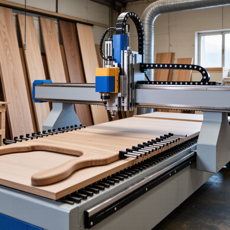
| Head–Head | Both rotary axes are integrated into the spindle head; the worktable remains fixed. | Commonly available in panel-oriented sizes such as approximately 1,300 × 2,500 mm, with larger custom envelopes also possible. | Often about ±120° to ±135° for the tilting axis and continuous or approximately ±360° for the swiveling axis. Actual limits depend on the head design. | Excellent access to the top, sides, and complex contours of a large stationary workpiece. Tool orientation changes are highly flexible. | Easy for heavy, oversized, or awkward parts because the workpiece does not rotate with the table. | Suitable for large sculptures, architectural components, molds, free-form furniture parts, and deep 3D reliefs. | Higher head clearance is required. The machine may need a larger Z-axis stroke, and cable routing and collision control are important. | Large solid-wood components, oversized carvings, architectural millwork, and deep undercut work. |
| Table–Table | The worktable provides both rotary axes, while the spindle head normally moves in X, Y, and Z. | Typically compact to medium size, often around 600–1,500 mm in X and 600–1,500 mm in Y, depending on table construction. | Frequently provides approximately ±110° to ±135° of tilt and continuous or approximately ±360° of rotation. | Very good access around small and medium workpieces, especially for machining multiple faces without manual repositioning. | Best for manageable workpieces that can be securely clamped to a rotating table. | Compact kinematic design, strong access to multiple faces, and good suitability for detailed components. | Rotary motion can reduce usable work envelope. Heavy or unbalanced workpieces may affect acceleration, accuracy, and table life. | Small sculptures, furniture components, instrument parts, prototypes, and detailed carved objects. |
| Head–Table | One rotary axis is mounted in the spindle head and the other is integrated into the worktable. | Commonly offered in medium-size formats, such as approximately 1,000–2,000 mm in X and 1,000–3,000 mm in Y. | Typical tilt is about ±100° to ±120° at the head or table, with the second axis often providing continuous or approximately ±360° rotation. | Good all-around access with a balance between overhead tool orientation and workpiece rotation. | Suitable for medium-weight parts; loading requirements depend on which axis carries the workpiece. | Versatile configuration for general-purpose 3D machining and mixed production requirements. | Rotary-axis limits and work-envelope loss must be checked carefully because the two axes are split between the head and table. | General woodworking, curved furniture parts, medium-sized sculptures, molds, and varied job-shop work. |
| Trunnion Table | A rotary table is supported by side bearings and tilts the workpiece around a horizontal axis; a second rotary axis turns the table. | Usually compact to medium, with the usable envelope reduced by the trunnion structure and the diameter of the rotary table. | Common tilt ranges are approximately +30°/−110° or ±110°; the rotary axis is often continuous or approximately ±360°. | Strong access to multiple faces and angled surfaces, but the trunnion frame can obstruct very low or side-oriented toolpaths. | Requires careful clamping and clearance planning; part size is limited by table diameter, height, and swing clearance. | Good rigidity and repeatability for smaller components, especially when consistent multi-face machining is required. | Less suitable for very large panels or tall parts. Collision checks must include the trunnion supports and clamps. | Compact furniture parts, turned-and-carved components, small molds, and precision multi-face machining. |
| Gantry Head–Head | A moving gantry carries a multi-axis spindle head, while the workpiece is supported on a fixed bed. | Often available with large working areas, such as approximately 2,000–4,000 mm in X and 3,000–8,000 mm in Y, depending on machine design. | Tilting capability is commonly about ±110° to ±135°; the swivel axis may be continuous or limited by head and cable design. | Excellent access for large, complex surfaces and long parts because the tool orientation changes while the workpiece remains fixed. | Well suited to large or heavy workpieces that are difficult to rotate. | Large capacity, flexible tool orientation, and effective machining of long architectural or sculptural parts. | Requires a large installation area. Gantry stiffness, vibration control, spindle power, and Z-axis clearance are critical. | Large timber beams, architectural panels, oversized sculptures, boat components, and full-scale prototypes. |
| 5-Axis Positioning: 3+2 | The rotary axes position the tool or workpiece, then the machine performs a conventional three-axis cutting operation. | Usually retains more practical cutting capacity than fully simultaneous 5-axis machining, but the rotary setup can still reduce clearance. | Rotary ranges vary widely; approximately ±90° to ±120° tilt and continuous or indexed rotation are common design targets. | Good access to selected faces and angled surfaces, but the tool axis does not continuously change during the cutting pass. | Efficient for parts that can be machined in several fixed orientations with secure clamping. | Lower programming complexity, easier operator training, and often lower software and maintenance requirements than fully simultaneous machining. | Cannot efficiently produce every continuously changing undercut or compound surface in one uninterrupted toolpath. | Cabinet components, angled joinery, multi-face drilling, fixed-angle carving, and repeatable production work. |
| Fully Simultaneous 5-Axis | All three linear axes and both rotary axes move together during the cutting process. | Available in compact, medium, and large formats; the practical envelope depends on rotary-axis geometry and collision limits. | Commonly offers approximately ±90° to ±135° tilt with continuous or near-continuous rotation, subject to singularities and mechanical limits. | Maximum cutting access for continuously changing surfaces, compound curves, deep undercuts, and complex 3D geometry. | Requires robust fixturing and accurate workpiece measurement because cutting forces and tool orientation change continuously. | Reduces repositioning, improves surface continuity, and can shorten tool reach for complex forms. | Requires advanced CAM software, accurate post-processing, collision simulation, careful machine calibration, and higher operator skill. | Complex sculptures, organic furniture, molds, artistic reliefs, aerodynamic forms, and high-value custom parts. |
| Continuous Rotary Woodworking Cell | A 5-axis spindle is combined with a dedicated rotary fixture, indexing system, or automated loading arrangement. | Usually optimized for repeatable part sizes rather than maximum sheet capacity; envelope depends on the rotary fixture and automation layout. | Often provides continuous rotation on one axis and approximately ±90° to ±120° on the tilting axis. | Very good access around rotational or near-rotational parts, with reduced manual repositioning between operations. | Designed for repeatable loading, dedicated fixtures, and stable production workflows. | Supports consistent cycle times, repeatability, and unattended or semi-automated production. | Less flexible for frequently changing part sizes. Fixture design, dust extraction, guarding, and automation integration add cost and complexity. | Repeated sculptural components, turned furniture elements, production carving, and standardized custom parts. |