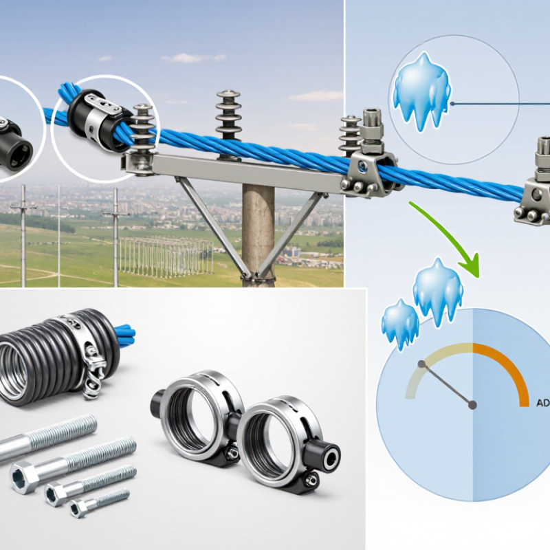
Reliable aerial fiber depends on more than the cable itself. The Adss Clamp must hold the cable securely without exceeding its permitted load or damaging its outer sheath. The stakes are growing: the International Telecommunication Union’s Facts and Figures 2024 report estimates that 5.5 billion people use the internet. As networks extend into more communities, small hardware choices can affect long-term reliability.
Choosing a clamp starts with the cable manufacturer’s specifications. Check the cable’s outside diameter, recommended support method, allowable tension, and planned span. Then consider the route: pole spacing, wind exposure, possible ice loading, and changes in elevation can all influence the required holding force. IEEE 1222-2019 provides a technical framework for all-dielectric self-supporting (ADSS) optical fiber cables, but it does not replace project-specific cable and hardware guidance. Verify that the clamp manufacturer lists the exact cable range and intended installation conditions. A close-looking fit is not proof.
Small parts matter. An undersized clamp may compress the sheath; an oversized one may not grip reliably. Yet diameter alone is not enough. Review installation instructions, compatible fittings, and any specified torque or tension limits with the supplier or project engineer. Field conditions rarely match a tidy drawing perfectly, and that deserves a second look. Careful selection gives crews a practical starting point and helps keep the cable supported as conditions change.
Span, cable diameter, and rated tensile strength (RTS) must be checked together. A longer span increases tension, but wind, ice, temperature, and sag limits also affect the load. Use the project’s NESC loading criteria and the cable manufacturer’s span-tension data; IEEE 1222 provides an industry reference for ADSS cable design and testing. Do not treat a clamp’s advertised span rating as universal. It depends on the cable and site conditions.
For example, a project worksheet might list a 250 m span, a 12 mm cable diameter, and 20 kN RTS. These are illustrative values, not standard design targets. Select a clamp specified for the cable’s actual diameter and compatible with the calculated support load. Check its published diameter range and rated holding capacity against the cable supplier’s requirements. A mismatch can crush the sheath or allow slippage.
Small mismatch. Big consequence.
Field crews should verify cable markings and measure the jacket before installation; nominal diameter can differ from the actual finished cable. Compare the design assumptions with local loading criteria and the IEEE 1222 cable specification, then confirm the clamp selection with the project engineer. One detail is easy to overlook: RTS describes cable strength, not a safe working load for every clamp. Apply the required design factors, and document any assumptions that remain uncertain.