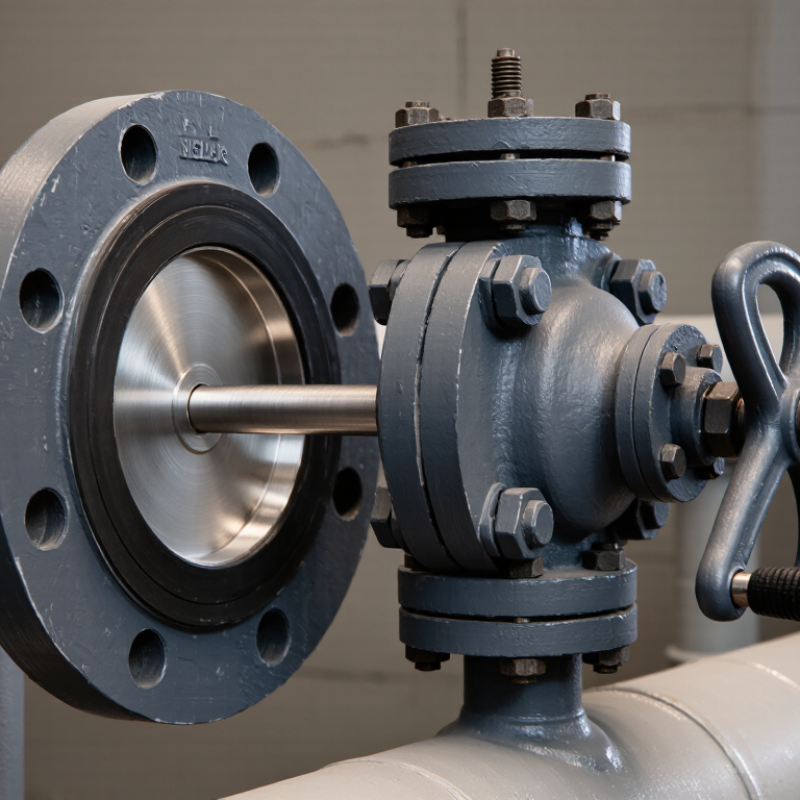
| Service and Medium | Identify the fluid or gas, operating temperature, pressure, concentration, suspended solids, and any cleaning chemicals. | Confirm that the body, disc, shaft, seat, and fasteners are suitable for the complete service conditions. Do not assume cast iron is suitable for every corrosive or abrasive medium. | Check material compatibility before installation. Inspect wetted parts regularly if the medium can cause corrosion, erosion, or seat damage. |
| Pressure and Temperature | Record normal and maximum operating pressure, temperature, pressure surges, and differential pressure across the valve. | Use the valve’s published pressure–temperature limits and differential-pressure ratings. These vary by design, size, materials, and applicable standard. | Do not use a general pressure class as a substitute for the specific manufacturer’s rating. Consider water hammer and other pressure transients. |
| Valve Size and Flow | Verify pipe size, required flow, allowable pressure loss, and whether the valve will be used for isolation or throttling. | Select a size and flow characteristic appropriate to the system. A butterfly valve may be used for throttling only when its design and service conditions permit it. | Confirm that the disc can rotate through its full travel without contacting pipe linings, nearby fittings, or other obstructions. |
| Body and Connection Style | Check the required wafer or lug configuration, flange standard, face-to-face dimensions, and available installation space. | Match the valve to the piping and flange arrangement. A lug-style valve is suitable for end-of-line service only when the valve is specifically rated for that condition. | Confirm bolt size, length, and access before installation. Follow the valve instructions for flange alignment and tightening sequence. |
| Body Material | Determine whether cast iron is appropriate for the system’s mechanical loads, pressure, temperature, and installation environment. | Cast iron is rigid but comparatively brittle and can be damaged by impact, excessive piping stress, or mishandling. Consider ductile iron or another material if the service requires greater impact resistance. | Support and align piping independently as required. Avoid striking the valve body or using it to correct pipe misalignment. |
| Disc, Shaft, and Seat | Check disc and shaft materials, seat material, media compatibility, temperature range, and required leakage performance. | Select materials for the actual fluid and operating conditions. Resilient seats can provide tight shutoff, but their suitability depends on temperature, chemicals, and pressure. | Inspect the seat and disc for cuts, deposits, corrosion, or wear. Replace damaged parts according to the valve maintenance instructions. |
| Actuation and Control | Decide between a lever, gear operator, pneumatic actuator, or electric actuator; note operating frequency and control requirements. | Size the operator or actuator using the required torque for the valve size, differential pressure, seat, and service—not valve diameter alone. | Provide access for operation and maintenance. For powered actuation, verify the supply, control signals, fail position, and any required position indication. |
| Flow Direction and Shutoff | Check whether the valve must seal in one or both directions and whether it will face reverse pressure or dead-end service. | Verify the permitted flow direction and pressure differential for the specific valve. Do not presume bidirectional shutoff or dead-end suitability. | Install in the orientation specified by the manufacturer. Confirm that the selected seat and valve configuration meet the required isolation duty. |
| Installation and Clearance | Check pipeline alignment, flange condition, disc clearance, actuator orientation, and nearby elbows or fittings. | Use the installation instructions for the exact valve design. Confirm whether separate flange gaskets are required; some resilient-seated designs use an integral liner or seat as the sealing element. | Keep the disc slightly open during installation if instructed. Center the valve between flanges and tighten bolts evenly in a cross pattern to avoid uneven loading. |
| Operation and Cycling | Assess the expected number of operating cycles, speed of operation, and potential for pressure surges. | Choose an operator suited to the duty and avoid rapid closure where it could create damaging pressure transients. | Operate through the intended travel without forcing the lever or actuator against a mechanical stop. Investigate abnormal torque or vibration promptly. |
| Maintenance and Isolation | Consider inspection access, spare-part availability, maintenance intervals, and whether the line can be safely isolated. | Choose a design that can be inspected and serviced within the site’s safety and maintenance procedures. | Before inspection or service, isolate the line, relieve pressure, drain or vent the system as appropriate, and verify a safe condition. Check fasteners, external corrosion, seat condition, and actuator function. |
| Standards and Documentation | Confirm applicable piping, dimensional, testing, and material requirements for the project and jurisdiction. | Request documentation for dimensions, materials, pressure–temperature limits, testing, and installation requirements for the selected valve. | Keep the valve data and maintenance records accessible so that future replacement parts and operating limits can be verified. |