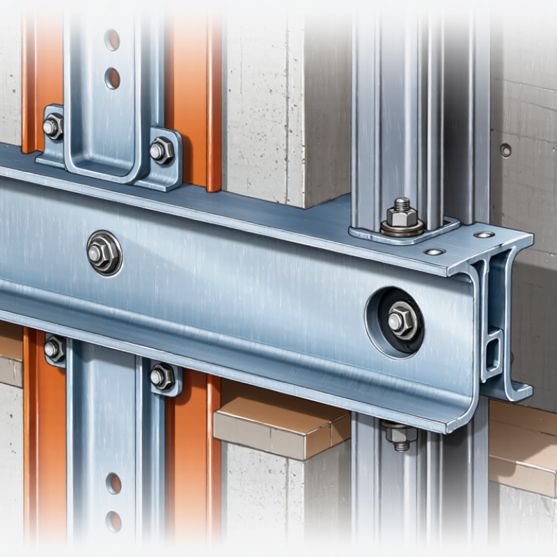
| Elevator load | Rated car load, counterweight arrangement, and the loads transferred to each guide rail | Passenger elevators commonly have rated loads such as 630, 1,000, or 1,600 kg. These figures describe car capacity, not the load on an individual bracket. | Higher loads and different suspension arrangements can increase guide-rail reactions. Brackets and their fixings must be selected for calculated reactions, not rated capacity alone. | Obtain rail reaction forces and support loads from the elevator design calculations. |
| Rail profile and dimensions | Rail type, nominal head width, height, foot dimensions, and fixing details | Common nominal rail head widths include approximately 70, 75, 89, and 90 mm. Exact dimensions and profile designations vary by rail type and applicable specification. | The bracket must match the rail profile and provide compatible clip or fastening geometry without obstructing the guide shoe or rail joint. | Check the rail drawing and the bracket’s specified compatible profiles; do not select by head width alone. |
| Rated speed and operation | Rated speed, starts per hour, travel height, and expected duty | A low-rise passenger lift may operate at about 1 m/s; higher-speed installations require a project-specific assessment of dynamic effects. | Speed, duty, and travel can affect vibration, dynamic forces, and alignment requirements. They may influence bracket strength, stiffness, and spacing. | Use the project’s design loads and applicable elevator and building requirements. |
| Preliminary bracket spacing | Vertical distance between successive rail supports | About 1.5–2.5 m may be used as an early layout range in some installations; this is not a universal or approved spacing. | Closer supports may be needed for higher loads, greater dynamic effects, rail-joint locations, or less rigid supporting construction. | Determine final spacing by calculation using rail properties, loads, fixing capacity, and project requirements. |
| Supporting structure | Concrete, structural steel, masonry, or another approved substrate; wall thickness and condition | Record substrate strength, edge distances, embedment depth, and the locations of reinforcement or structural members. | The bracket is only as reliable as its anchors and supporting structure. A bracket suitable for concrete may not suit a steel beam or masonry wall. | Check anchor design, substrate capacity, installation details, and any required pull-out or inspection procedures. |
| Operating environment | Temperature, moisture, corrosion exposure, dust, and indoor or outdoor location | Dry indoor shafts differ from damp, coastal, or chemically exposed environments. | Environment affects material, coating, corrosion protection, and the long-term condition of fasteners and rail connections. | Specify suitable materials and protective finishes for the actual exposure conditions. |
| Installation and alignment | Bracket adjustment range, rail plumbness, shaft tolerances, and joint arrangement | Confirm that the bracket allows the required adjustment while maintaining secure rail clamping and access for installation. | Insufficient adjustment can make rail alignment difficult; poor clamping or joint placement can affect smooth operation. | Review installation drawings, rail alignment tolerances, and manufacturer instructions for the selected components. |