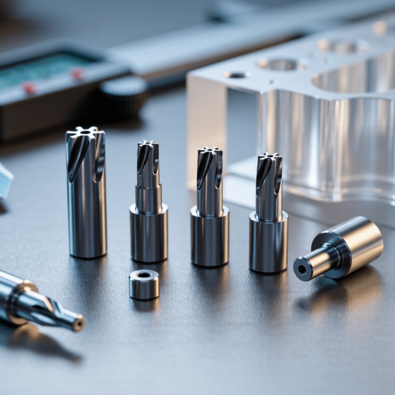
| Core pin function | Forms internal holes, cavities, slots, bosses, and other negative features in an injection-molded or die-cast part. | The pin geometry directly affects the finished part's dimensions, appearance, and ejection behavior. | Define the required molded feature first, then specify the pin's diameter, length, tip geometry, and fit. |
| Common material | Hardened tool steel; pre-hardened alloy steel; corrosion-resistant stainless tool steel for demanding environments. | Material determines wear resistance, toughness, corrosion resistance, thermal stability, and service life. | Use hardened steel for abrasive or high-volume molding; consider corrosion-resistant steel when moisture, corrosive resin, or frequent cleaning is expected. |
| Hardness | Common hardened tool-steel core pins are often specified around 45–60 HRC, depending on steel grade and application. | Higher hardness generally improves wear resistance but may reduce toughness and increase sensitivity to impact or improper handling. | Match the hardness to resin abrasiveness, production volume, operating temperature, and risk of side loading. |
| Nominal diameter | Select from the required molded-hole size and the available standard or custom diameter range. | Diameter controls the final feature size and influences buckling resistance, heat transfer, and pin strength. | Specify finished diameter, allowable tolerance, measurement temperature, and whether the dimension is before or after coating. |
| Diameter tolerance | Typical precision-ground pin tolerances may range from approximately ±0.005 mm to ±0.02 mm, depending on size and supplier capability. | The pin tolerance contributes to the dimensional accuracy of the molded feature and the clearance in the mold. | Use the tightest practical tolerance; verify the required mold fit rather than specifying unnecessarily expensive precision. |
| Overall length | Determined by the mold stack, cavity depth, support arrangement, and required retention length. | An unsuitable length can cause interference, insufficient support, poor alignment, or excessive deflection. | Provide a dimensioned drawing showing the forming length, locating length, shoulders, and any required relief. |
| Working length-to-diameter ratio | Long, slender pins require additional design review; the acceptable ratio depends on support, load, material, and molding conditions. | A high slenderness ratio increases the risk of bending, buckling, vibration, and premature wear. | Reduce unsupported length, increase diameter, add guidance, or use a stepped and supported design where practical. |
| Head and retention style | Straight pin, shoulder pin, headed pin, stepped pin, or custom retaining geometry. | The retention style determines installation position, axial location, replacement method, and compatibility with the mold plates. | Match the head, shoulder, and locating features to the mold design; confirm transitions are free from stress-concentrating sharp corners. |
| Tip geometry | Flat end, radius, chamfer, tapered end, stepped end, or special forming profile. | The tip forms the molded feature and affects filling, demolding, stress concentration, and cosmetic quality. | Use a drawing or CAD profile for non-flat ends; define radius, angle, blend, and surface-finish requirements explicitly. |
| Surface finish | Precision-ground surface; optional polishing or coating for specialized applications. | A smooth, consistent surface can reduce friction, sticking, drag marks, and resin buildup. | State the required roughness or visual finish and identify which surfaces require polishing or special treatment. |
| Straightness and concentricity | Controlled according to pin diameter, length, mold fit, and feature-accuracy requirements. | Poor straightness or concentricity can create uneven clearance, flash, nonuniform wall thickness, and premature failure. | Add measurable limits to the drawing and request inspection records for long, small-diameter, or high-precision pins. |
| Operating temperature | Consider the mold temperature, melt temperature, cycle time, and thermal cycling of the selected material. | Heat can affect hardness, dimensional stability, oxidation, lubrication, and clearance. | Confirm the steel and heat treatment are suitable for the actual process temperature and cooling conditions. |
| Resin or material being molded | Standard thermoplastics, glass-filled polymers, mineral-filled polymers, engineering plastics, or corrosive materials. | Glass and mineral fillers accelerate abrasive wear; some resins and additives increase corrosion risk. | Provide resin grade, filler percentage, additives, and expected production volume when requesting a quotation. |
| Clearance and mold fit | Fit depends on pin diameter, guide-bore size, thermal expansion, alignment, and the need to prevent flash. | Insufficient clearance may cause seizure; excessive clearance may allow flash or feature misalignment. | Have the mold designer define the fit and account for temperature, lubrication, and expected wear. |
| Quality documentation | Material certificate, heat-treatment record, dimensional inspection report, hardness report, and coating certificate when applicable. | Documentation provides traceability and confirms that the delivered pins meet the approved specification. | Specify required documents before placing the order and request lot identification on packaging and inspection records. |
| Supplier evaluation | Review manufacturing capability, grinding accuracy, heat-treatment control, inspection equipment, lead time, and replacement support. | Supplier capability affects consistency, delivery reliability, total cost, and the risk of mold downtime. | Compare suppliers using the same drawing, tolerances, documentation requirements, sample approval process, and service expectations. |
| Packaging and storage | Protective sleeves, corrosion-inhibiting packaging, individual identification, and dry, clean storage. | Small precision pins can be damaged by impact, contamination, rust, or mixing of similar dimensions. | Require protective packaging, clear part identification, rust prevention, and controlled storage before installation. |