Request Quote

Request a quote from Nidec Drive Technology America Corporation.

This quote form is intended for customers and partners in North America seeking information about Nidec Drive Technology America Corporation’s Precision Gearing Technologies. For inquiries related to the Nidec motor group division or from outside this region, please visit the global Nidec Group website to find the appropriate regional or product-specific contact.

Subscribe to Nidec Newsletter

Subscribe to our email newsletter to stay current with our precision gearing solutions, featured products, company updates, and industry news.

How Does an EDI Water System Work?

An Edi Water System turns pretreated feedwater into high-purity water using electricity, ion-exchange resin, and selective membranes. The EDI Water System Working Principle is straightforward: dissolved ions migrate through membranes under a direct-current field, while resin helps transport them. The result is a continuous polishing process, usually installed after reverse osmosis. No chemical regeneration is normally needed. The details matter.

Why does this technology attract attention? The Semiconductor Industry Association reported that global semiconductor sales reached $627.6 billion in 2024. Semiconductor manufacturing depends on tightly controlled ultrapure water for rinsing wafers and protecting sensitive processes. ASTM D5127-13(2021), a guide for ultrapure water used in electronics and semiconductor industries, also reflects how demanding these applications can be. Pharmaceutical and power-generation facilities use high-purity water too, though their required specifications differ.

This article explains the main components, water flow, ion removal, and operating conditions behind EDI. It also examines how feedwater quality, recovery, and monitoring affect performance. A small conductivity change can signal a process problem. EDI is not magic, though. It cannot compensate for poor pretreatment, incorrect system design, or neglected maintenance. Understanding the operating principle helps readers assess where the technology fits—and where it may fall short.

How Does an EDI Water System Work?

What an EDI Water System Is and Where It Fits in Water Treatment

An EDI water system uses ion-exchange resin, selective membranes, and direct current to remove dissolved ions from water. In a typical high-purity treatment train, it sits after reverse osmosis (RO), not in place of it. RO removes most dissolved salts; EDI polishes the remaining ions and continuously regenerates its resin electrically. No acid or caustic is normally needed for resin regeneration within the EDI unit.

That is the polishing stage. Feed quality matters: changes in hardness, carbon dioxide, or silica can affect performance, so operators monitor conductivity and product-water resistivity. EDI does not remove every contaminant, and it is not a substitute for suitable pretreatment.

The U.S. Geological Survey estimated total U.S. water withdrawals at 322 billion gallons per day in 2015, including 14.8 billion gallons per day for industrial use (USGS Circular 1441, Estimated Use of Water in the United States in 2015). Those figures describe water use, not EDI output.

Still, they underline why industrial systems must track both water quality and losses. A practical design also checks the RO permeate, EDI concentrate, and storage loop; a tidy equipment diagram can hide real operating variation.

How Pretreated Water Enters the EDI Module

How Does an EDI Water System Work?
How Pretreated Water Enters the EDI Module

Pretreated water usually reaches the electrodeionization (EDI) module after reverse osmosis has removed most dissolved salts. The Water Quality Association reports that reverse-osmosis systems commonly reject about 95–99% of dissolved salts, though performance depends on feedwater and operating conditions. The remaining water is not ion-free. It can still contain traces of sodium, chloride, hardness, carbon dioxide, or silica. Small amounts matter.

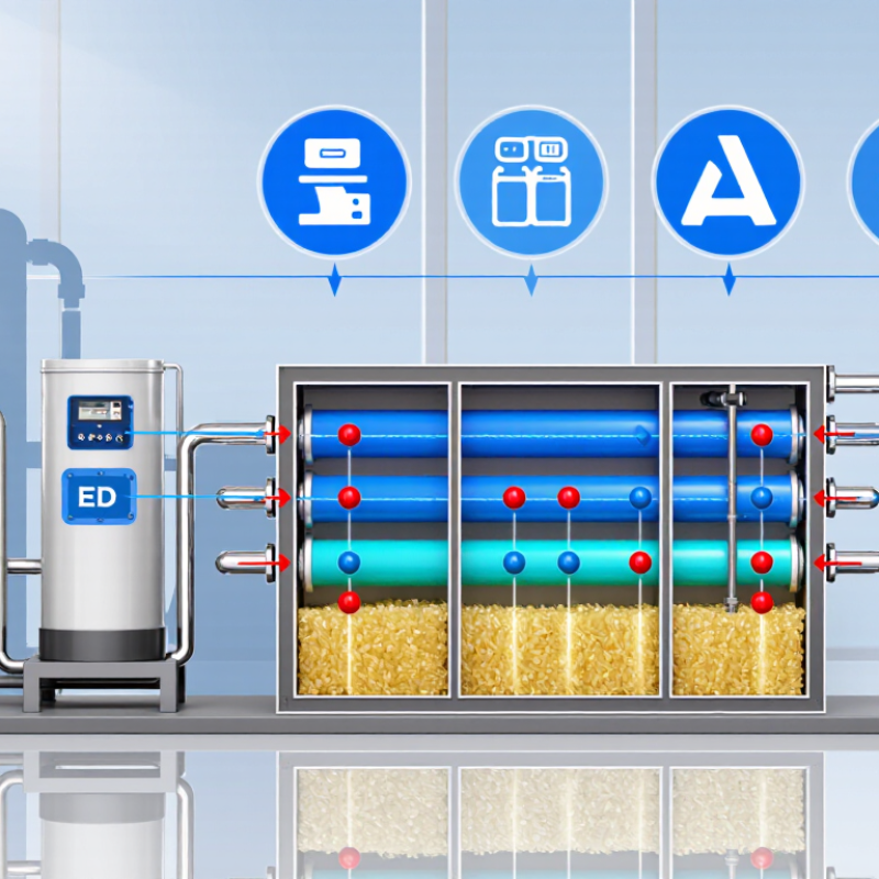
At the module inlet, a distributor spreads the permeate across narrow channels filled with ion-exchange resin and separated by selective membranes. A direct-current field draws positive and negative ions through different membranes toward concentrate channels; the resin helps carry ions between them. Flow and inlet chemistry must stay within the module’s specified operating range, especially conductivity, hardness, and carbon dioxide. Otherwise, scaling or reduced product-water quality can follow. Exact limits differ by design, so a generic target can mislead. Real plants are messier. Operators check inlet conductivity and pressure, and they watch for sudden shifts after an RO change or maintenance. A little measurement detail is easy to overlook.

How Does an EDI Water System Work? — How Pretreated Water Enters the EDI Module

Representative conductivity at the EDI feed and product outlets

Pretreated reverse-osmosis permeate enters the EDI module’s dilute compartments. An electric field drives dissolved ions through ion-exchange membranes into concentrate compartments, while purified water flows out as product. Values shown are representative examples; actual conductivity depends on feed quality and system design.

How Ion-Exchange Resins and Membranes Remove Dissolved Ions

How Does an EDI Water System Work?

How Ion-Exchange Resins and Membranes Remove Dissolved Ions

An electrodeionization (EDI) system uses ion-exchange resins, selective membranes, and direct current to reduce dissolved ions in pretreated water. Water flows through a resin-filled compartment between cation- and anion-selective membranes. The resin helps ions travel through the compartment, while the membranes guide positively and negatively charged ions toward separate concentrate channels. Small ions move. The purified stream exits continuously, while the concentrate stream carries away much of the removed ionic load.

Tips: Check feed-water quality before operation. Excess hardness or suspended particles can foul the system. Track product-water conductivity and flow; changes can signal a process issue. EDI is not a substitute for every pretreatment step.

Inside the unit, an electric field drives cations through cation-selective membranes and anions through anion-selective membranes. These ions collect in concentrate channels rather than returning to the product stream. Water splitting near resin and membrane interfaces produces hydrogen and hydroxide ions, which help restore the resin’s exchange sites during operation. Performance still depends on stable feed conditions and correct system design. EDI mainly targets ionized substances, so uncharged contaminants may require other treatment methods. In practice, readings deserve attention, but one unusual reading alone may not explain the cause.

How Direct Current Continuously Regenerates the Resins

How Does an EDI Water System Work?

How Direct Current Continuously Regenerates the Resins

Inside an electrodeionization (EDI) stack, water flows through narrow compartments packed with ion-exchange resin. A direct-current field pulls dissolved ions toward oppositely charged electrodes. Selective membranes let those ions leave the product-water path and enter a concentrate stream. The resin acts like a fast-moving handoff point: it captures ions, then releases them under the electric field. Meanwhile, water splitting creates hydrogen and hydroxide ions, which restore the resin’s exchange sites. No chemical regeneration cycle is needed. The process keeps running as long as water and power are supplied.

The performance target can be demanding. ASTM D5127-13(2023), a guide for ultrapure water in electronics manufacturing, describes high-purity applications where resistivity approaches 18.2 megohm-centimeters at 25°C. That figure is close to pure water’s theoretical limit, not a promise every EDI unit will meet. Feed-water quality matters: hardness, carbon dioxide, and silica can raise the load on the stack. Operators monitor product resistivity and concentrate flow, while watching for gradual changes. Small details count. A drifting reading may reflect a feed problem, not failed resin. That distinction is easy to miss.

How Product Water and Concentrate Leave the System

How Does an EDI Water System Work?
How Product Water and Concentrate Leave the System

Inside an electrodeionization (EDI) module, feed water passes through chambers containing ion-exchange resin and selective membranes. Direct current moves dissolved ions across the membranes into separate concentrate channels. Water with fewer ions remains in the product chambers. The two streams leave through different outlets. Product water then flows to storage or the next treatment step. Exact outlet arrangements vary by system design.

The concentrate outlet carries away the ions removed from the product stream. Some systems send this water to drain; others recirculate part of it, depending on the design and operating conditions. Flow rates matter. Too little concentrate flow can reduce ion removal or encourage scaling, while excess flow may waste treated water. Operators typically check product conductivity, concentrate flow, and pressure. A quiet outlet is not proof of good performance.

Tips: Check that both outlet lines are open and flowing as specified. Compare readings with the equipment’s operating guidance, not just yesterday’s numbers. If conductivity rises, inspect flow and pressure before adjusting settings. The balance can be subtle, and real systems do not always behave neatly.

How Does an EDI Water System Work? – How Product Water and Concentrate Leave the System
Stream Where It Flows What Happens Inside the EDI Stack What Leaves the System Typical Monitoring
Feed water Enters the EDI module, usually after reverse osmosis pretreatment. Flows through alternating dilute and concentrate compartments. Pretreatment helps limit scaling and fouling. Splits into product, concentrate, and—depending on module design—electrode-rinse flows. Flow, pressure, temperature, conductivity, and feed-water quality.
Product water (dilute stream) Passes through the dilute compartments and exits the product outlet. Dissolved ions move out of the dilute stream through ion-exchange membranes under a direct-current electric field. Ion-exchange resin helps transport ions within the compartments. A demineralized water stream sent to storage, distribution, or another treatment step, as required by the process. Product conductivity or resistivity, flow, and pressure. Target quality depends on feed water and system design.
Concentrate stream Flows through the concentrate compartments, alongside the dilute compartments, and exits through the concentrate outlet. Receives ions that migrate across the membranes from the dilute compartments. The stream carries these ions away from the product-water path. Leaves as a more ion-rich reject stream. Depending on the installation, it may be sent to drain or partly recirculated. Concentrate flow, pressure, conductivity, and evidence of scaling or blockage.
Electrode-rinse stream Flows through the electrode compartments in designs that use a separate rinse circuit. Provides a path for electrode reactions and helps keep electrode compartments flushed. Its arrangement is module-specific. Leaves through a dedicated rinse outlet; it is separate from the product-water outlet. Rinse flow and any operating limits specified by the module manufacturer.