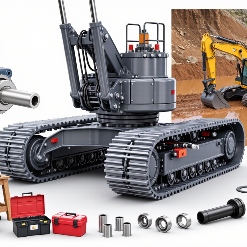
| Final-drive role | A crawler final drive typically combines a hydraulic travel motor with a planetary reduction gearbox. It converts motor speed into lower-speed, higher-torque rotation at the drive sprocket. | Check the motor, gearbox, brake, mounting interface, and sprocket connection as a compatible assembly. | Match the complete drive to the machine’s hydraulic system and undercarriage—not just to a stated torque figure. |
| Machine fit and mounting | Confirm machine model and serial-number range, mounting bolt pattern, pilot diameter, shaft or spline dimensions, port locations, and sprocket fit. | Compare drawings and measured dimensions; verify rotation direction and hose-port orientation. | Correct torque with an incompatible mounting interface will not produce a workable replacement. Confirm fitment with the machine or drive documentation. |
| Hydraulic pressure | Identify the machine’s available travel pressure and the drive motor’s permitted continuous and peak pressure ratings. | Hydraulic motor torque is approximately: T = Δp × Vg × ηm ÷ (2π), where Δp is pressure difference in pascals, Vg is displacement in cubic metres per revolution, and ηm is mechanical efficiency. | Use the continuous rating for sustained work. Peak pressure is not a substitute for a continuous-duty rating. |
| Hydraulic flow and travel speed | Check flow available to each travel motor, including any flow-sharing or control limits. | Approximate motor speed: n = Q × ηv ÷ Vg, with flow Q in volume per minute and displacement Vg in the same volume per revolution. Output speed is approximately motor speed divided by reduction ratio. | More flow generally increases travel speed; motor displacement and reduction ratio determine how that speed translates to the sprocket. |
| Gear reduction ratio | Compare the required travel speed and sprocket torque with the drive’s reduction ratio. | Output torque ≈ motor torque × reduction ratio × gearbox efficiency. Output speed ≈ motor speed ÷ reduction ratio. | A higher reduction ratio increases torque multiplication but reduces output speed. Select against the machine’s specified travel performance and duty requirements. |
| Illustrative torque calculation | Example only: a 200 cm³/rev motor operating at a 250 bar pressure difference, with assumed mechanical efficiency of 0.90. | Estimated motor torque: approximately 72 N·m. With a 60:1 reduction ratio and assumed gearbox efficiency of 0.90, estimated output torque is approximately 3,860 N·m. | This calculation illustrates the relationship between pressure, displacement, reduction, and efficiency. It is not a rating for a particular drive or machine. |
| Sprocket torque and drawbar force | Use the drive sprocket’s effective pitch radius and the machine’s traction limits. | Approximate sprocket force: F = output torque ÷ effective sprocket radius. For the example above and a 0.18 m radius, the theoretical force is about 21.5 kN. | Actual usable tractive force may be lower because of track-ground traction, machine weight, grade, soil conditions, and hydraulic or control limits. |
| Braking and holding | Verify the travel motor’s brake type, release pressure, holding capacity, and compatibility with the machine’s brake circuit. | Compare brake specifications with the machine manufacturer’s requirements; check whether the brake is spring-applied and hydraulically released. | Do not infer safe holding performance from gearbox torque alone. Brake requirements depend on machine design and operating conditions. |
| Duty cycle and heat management | Assess continuous travel, frequent starts and stops, slope work, counter-rotation, and ambient temperature. | Check continuous and intermittent ratings, allowable case-drain flow, oil-temperature limits, and required hydraulic oil grade in the applicable documentation. | Repeated high-load operation can generate heat and shorten component life if the drive or hydraulic circuit is not rated for the duty. |
| Contamination and sealing | Inspect shaft seals, housing protection, case-drain routing, and the cleanliness requirements for hydraulic connections. | Follow the specified hydraulic-fluid cleanliness and filtration requirements; keep open ports capped during installation. | Water, dirt, and metal particles can damage motor surfaces, bearings, and seals. Correct installation and clean oil help protect the drive. |
| Final verification | Confirm all ratings and dimensions against the machine and drive technical documents before ordering or installation. | Verify pressure, flow, torque, speed, ratio, brake, mounting, ports, sprocket interface, and operating limits together. | There is no universal best crawler final drive: the suitable unit is the one that meets the machine’s verified fitment and duty requirements. |