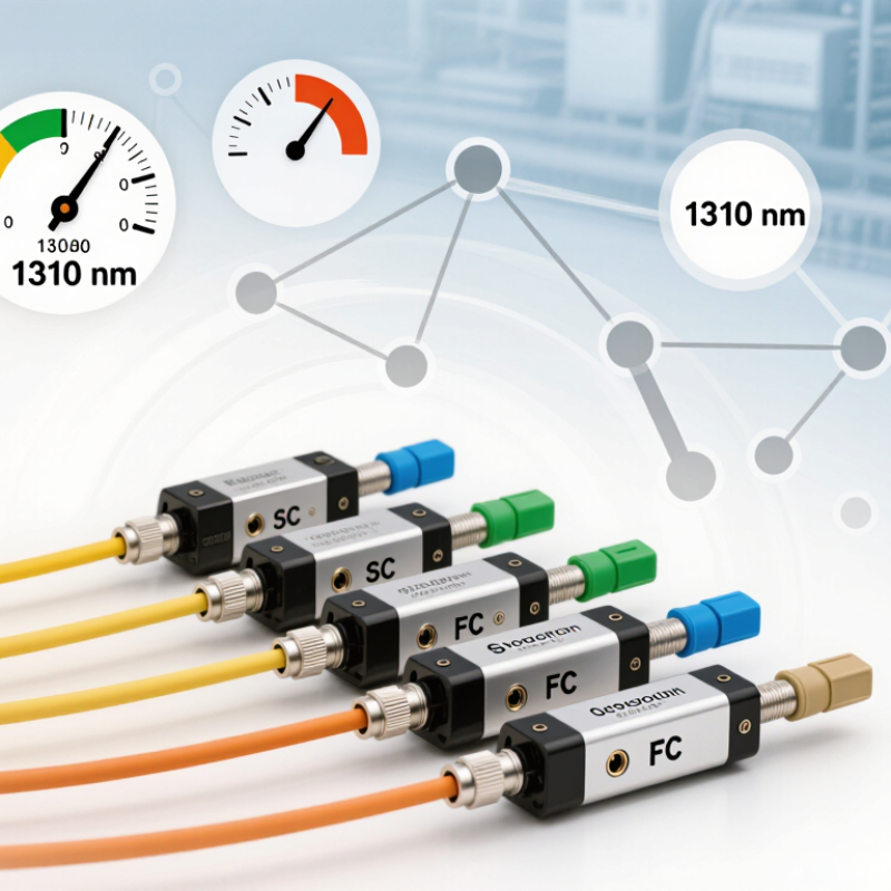
| Fixed power reduction for a stable link | Fixed inline attenuator | Nominal attenuation, operating wavelength, connector interface | 1–20 dB; common values include 3, 5, 10, 15 and 20 dB | Provides a simple, low-maintenance method for reducing excessive received optical power. |
| Laboratory testing or receiver-margin adjustment | Variable optical attenuator (VOA) | Attenuation range, adjustment resolution, repeatability and control method | 0–30 dB or 0–60 dB; manual or electronically controlled | Allows controlled optical-power sweeps for receiver sensitivity, overload and system-margin tests. |
| Single-mode telecom transmission | Single-mode fixed attenuator or single-mode VOA | Wavelength compatibility, insertion loss, return loss and fiber type | 1310, 1490, 1550 and 1625 nm; typically 9/125 µm fiber | The attenuator must match the optical band and maintain acceptable reflections on single-mode links. |
| Multimode data-center or short-reach link | Multimode attenuator | Fiber type, modal performance, wavelength and connector polish | 850 nm; commonly used with 50/125 µm multimode fiber | A single-mode attenuator may not provide the intended modal behavior when installed on a multimode link. |
| High-power transmitter or amplified optical system | High-power fixed attenuator or high-power VOA | Maximum optical input power, power density, thermal stability and wavelength | Confirm the manufacturer-rated power; standard telecom parts are often rated around +20 dBm, while specialized designs support higher levels | Exceeding the power rating can cause heating, permanent attenuation drift or component damage. |
| Dense wavelength-division multiplexing (DWDM) | Low-reflection attenuator specified for the C-band | Spectral flatness, wavelength range, return loss and channel uniformity | Approximately 1525–1565 nm for the conventional C-band | Wavelength-dependent attenuation can create unequal channel powers and reduce optical-system margin. |
| Passive optical network (PON) deployment | PON-compatible fixed attenuator | Upstream and downstream wavelength coverage, attenuation tolerance and return loss | Often requires support for 1310, 1490 and 1577 nm, depending on the PON generation | PON systems may use different wavelengths for upstream and downstream signals, so single-wavelength parts may be unsuitable. |
| Low-loss optical budget | Precision attenuator with low excess loss | Insertion loss excluding the specified attenuation | Commonly ≤ 0.5 dB for quality passive components; verify the actual datasheet value | Excess loss consumes link budget in addition to the intentional attenuation. |
| Reflection-sensitive equipment | Low-reflection attenuator with angled-polish connectors where appropriate | Return loss (RL), connector polish and reflectance stability | Target RL of ≥ 50 dB for demanding single-mode applications; the required value depends on the system | Lower reflections help limit interference, laser instability and measurement uncertainty. |
| Outdoor or temperature-variable installation | Temperature-stabilized or environmentally rated attenuator | Operating temperature, attenuation temperature coefficient and environmental sealing | Commercial equipment commonly covers about 0–70°C; industrial equipment may cover about −40–85°C | Temperature changes can alter attenuation, connector alignment and long-term measurement accuracy. |
| Field replacement and frequent reconnection | Connectorized fixed attenuator with a protected housing | Connector durability, keying, polarity, cleaning access and mechanical retention | Common interfaces include LC, SC and FC; select UPC or APC to match the network | Mechanical and connector compatibility reduce installation errors and repeated-service failures. |
| Automated test equipment or remote control | Motorized or electronically controlled VOA | Control interface, response time, calibration status, resolution and repeatability | Typical resolution: 0.01–0.1 dB; response time varies by design | Digital control enables repeatable test sequences and automated optical-power management. |