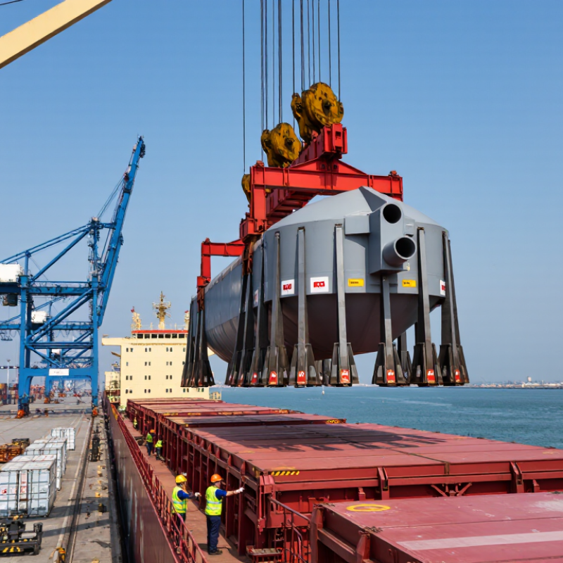
| Working Load Limit (WLL) | The WLL is the maximum permitted load under specified conditions. It is not the same as the breaking strength of the equipment. | Using equipment above its WLL can cause deformation, sling failure, dropped loads, and severe injury. | Confirm the marked WLL, lifting configuration, load weight, center of gravity, and applicable standard before purchase or use. |
| Two-Leg Sling Angle | For a symmetrical two-leg sling, approximate leg tension factors are: 90° from horizontal: 1.000; 60°: 1.155; 45°: 1.414; 30°: 2.000. | As the sling angle decreases, tension in each leg increases. At 30° from horizontal, each leg carries approximately twice the share calculated for a vertical arrangement. | Keep sling angles as large as practical and calculate leg tension before selecting the sling or lifting point. Avoid angles below 30° unless specifically engineered. |
| Load Balance and Center of Gravity | A suspended load remains stable only when the combined lifting arrangement keeps the center of gravity below the lifting point or within the support polygon. | An offset center of gravity can cause tilting, sliding, unexpected rotation, or uneven loading of sling legs. | Identify the center of gravity, use appropriate lifting points, and perform a controlled trial lift a few centimeters above the ground. |
| Sling Material Selection | Wire-rope slings provide high abrasion resistance; synthetic web slings are lightweight and can reduce surface damage; chain slings tolerate heat and rugged handling but are heavier. | Incorrect material selection can lead to cutting, abrasion, heat damage, chemical deterioration, or excessive deformation. | Match the sling material to load edges, temperature, chemicals, abrasion exposure, available headroom, and required flexibility. |
| Edge Protection | Synthetic slings can be cut by sharp or unprotected load edges, even when the total load is below the sling's rated capacity. | Cutting and localized pressure can cause sudden sling failure during lifting or movement. | Use purpose-designed corner protectors, sleeves, or softeners and ensure that protection cannot slip out during the lift. |
| Shackles and Connection Hardware | Shackles, hooks, master links, eyebolts, and lifting points must have compatible WLL ratings and suitable loading directions. | Side loading, point loading, improper pin seating, or incompatible components can substantially reduce capacity. | Check identification markings, pin condition, load direction, connection geometry, and compatibility of every component in the load path. |
| Inspection Before Use | Common rejection indicators include broken wires, stretched links, bent hooks, cracks, severe corrosion, cuts, heat damage, illegible markings, and unauthorized repairs. | Visible damage may indicate reduced strength or hidden internal deterioration. | Perform a documented pre-use inspection and remove damaged or unidentified equipment from service immediately. |
| Environmental Conditions | Temperature, ultraviolet exposure, moisture, chemicals, saltwater, and abrasive dust can affect rigging performance. Synthetic materials generally require stricter limits for heat and chemical exposure. | Environmental degradation can reduce capacity without obvious changes in the load weight. | Review manufacturer temperature and chemical limitations, protect equipment during storage, and select materials suitable for the destination environment. |
| Dynamic Loading | Sudden starts, stops, shock loading, load snagging, and impact can create forces greater than the static weight of the load. | Dynamic forces can overload slings, cranes, lifting points, and supporting structures. | Lift smoothly, eliminate slack before taking the load, avoid sudden direction changes, and never use rigging to drag or jerk a load. |
| Communication and Exclusion Zones | Only trained and authorized personnel should direct lifting operations, and personnel should remain clear of suspended loads. | Poor communication and people beneath suspended loads are major contributors to lifting incidents. | Define a signal system, appoint one designated signal person where required, barricade the lifting area, and prohibit travel beneath suspended loads. |
| Documentation and Traceability | Rigging equipment should be identifiable through durable markings, inspection records, rated capacity information, and applicable conformity documentation. | Without traceability, users cannot reliably verify capacity, inspection status, material suitability, or maintenance history. | Request readable markings, certificates or declarations required by the destination market, inspection records, and clear product specifications. |
| International Procurement | Requirements may vary by jurisdiction, industry, and application. Common references include recognized lifting-equipment standards, local occupational-safety rules, and port or site procedures. | Equipment that is acceptable in one market may require additional documentation, testing, marking, or operating controls in another. | Define the destination country, applicable regulations, operating environment, metric or imperial units, and required documentation before placing an order. |