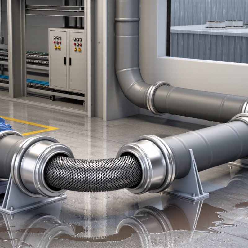
| Product Definition | LFMC consists of a flexible metallic core, typically made from galvanized steel or another corrosion-resistant metal, with a liquid-resistant nonmetallic jacket. | Useful when conductors must be routed around equipment, machinery, motors, pumps, or other components that move or require final-position adjustment. | The jacket must remain intact. Cuts, severe abrasion, crushed sections, or damaged fittings can compromise the liquid-resistant function. | Essential |
| Primary Protection Functions | Provides mechanical protection, a defined wiring pathway, flexibility, and resistance to specified environmental conditions when the complete assembly is properly installed. | Appropriate for short flexible connections between rigid raceways and equipment enclosures or between fixed equipment and vibrating machinery. | It is not a substitute for correct conductor insulation, overcurrent protection, enclosure ratings, or a suitable grounding and bonding path. | High |
| Common Installation Locations | Common locations include wet or damp areas, washdown zones, outdoor equipment, industrial machinery, HVAC equipment, pumps, compressors, and areas exposed to oil or coolants. | Choose the conduit only when its jacket, fittings, and installation method are suitable for the specific liquid, temperature, ultraviolet exposure, and mechanical conditions. | Environmental suitability is not universal. A conduit suitable for water exposure may not be suitable for aggressive chemicals, solvents, or high-temperature fluids. | High |
| Conduit Trade Size | LFMC is manufactured in standardized trade sizes. The internal usable area depends on the trade size, wall construction, and the number and type of conductors. | Determine the required size from conductor count, conductor dimensions, permitted raceway-fill rules, fitting space, and the expected pulling or routing conditions. | Do not select size by outside diameter alone. The smallest practical size may make conductor installation difficult and can increase the risk of insulation damage. | High |
| Conductor Fill | Raceway fill is limited by electrical installation rules. The permitted percentage depends on the number of conductors and the applicable code or standard. | Calculate fill using the actual conductor dimensions and the applicable jurisdictional requirements before ordering conduit and fittings. | Overfilling can make pulling difficult, damage insulation, reduce heat dissipation, and create a noncompliant installation. | Critical |
| Bend Radius | The minimum bend radius varies by conduit construction, trade size, fitting system, and manufacturer instructions. | Plan the route with gradual bends and enough space to install fittings without forcing the conduit into a sharper curve than permitted. | Exceeding the allowable bend can flatten the conduit, restrict conductor installation, damage the jacket, or reduce mechanical and liquid resistance. | Critical |
| Maximum Practical Flexing | LFMC is flexible, but most installations treat it as a protected connection rather than a continuously flexing cable system. | Use it for equipment connections and limited movement. For continuous robotic or repeated-motion applications, use a wiring system specifically rated for that service. | Repeated flexing can fatigue the metal core, jacket, conductors, or fittings. A flexible appearance does not automatically mean continuous-flex suitability. | High |
| Liquid Resistance | The liquid-resistant performance depends on the conduit jacket, connector, sealing method, and correct assembly of the entire raceway system. | Use listed liquid-tight fittings and install them according to the fitting instructions. Seal or orient terminations to prevent water migration where required. | A liquid-tight conduit body with an incorrectly installed connector is not a liquid-tight system. Water can enter through open ends, damaged jackets, or poorly sealed fittings. | Critical |
| Grounding and Bonding | The metallic raceway may be part of the equipment grounding and bonding path when the complete system is suitable, properly connected, and installed under the governing electrical requirements. | Use fittings designed for the conduit type and verify continuity across joints, enclosures, and equipment connections. Install a separate grounding conductor when required by the applicable rules or design. | Paint, corrosion, loose fittings, incompatible connectors, or excessive mechanical damage can interrupt electrical continuity. Never assume continuity without verification. | Critical |
| Fittings and Terminations | Connectors must match the conduit type, trade size, enclosure entry, environmental rating, and required grounding or bonding method. | Select fittings with appropriate sealing rings, locknuts, bonding components, and strain-relief features where applicable. | Mixing unapproved conduit and fitting systems can reduce pullout strength, liquid resistance, enclosure integrity, and grounding reliability. | Critical |
| Temperature Range | Allowable operating temperatures are determined by the conduit jacket, fittings, conductors, and installation conditions. Exact limits vary by product construction. | Check the product marking and technical documentation for ambient temperature, sunlight exposure, oil exposure, and installation-temperature limitations. | Excessive heat can harden or deteriorate the jacket and may require conductors with an appropriate temperature rating. Low temperatures can reduce flexibility. | High |
| Chemical and Oil Exposure | Resistance to oils, fuels, solvents, acids, alkalis, and process chemicals varies by jacket material and product construction. | Identify the actual chemical, concentration, exposure time, temperature, and cleaning method before selecting the conduit. | Do not infer chemical compatibility from the term “liquid-tight.” Confirm compatibility using the applicable product documentation or engineering review. | Critical |
| Outdoor and UV Exposure | Outdoor use requires a jacket and fitting system suitable for sunlight, rain, temperature changes, and the expected environmental conditions. | Use products identified for the intended outdoor exposure and protect routing from standing water, sharp edges, and unnecessary direct sunlight where appropriate. | UV aging, weathering, and water intrusion can reduce service life. Outdoor suitability should be verified rather than assumed. | High |
| Mechanical Protection | The metal core improves resistance to impact and crushing compared with many nonmetallic flexible raceways, but it is not damage-proof. | Use supports, guards, and suitable routing where the conduit may be exposed to impact, abrasion, vibration, or vehicle traffic. | Do not use damaged, kinked, flattened, or severely abraded conduit. Replace compromised sections instead of relying on the jacket to conceal damage. | High |
| Support and Routing | Flexible conduit requires support and must be routed to avoid unnecessary strain on fittings, terminals, and enclosure entries. | Provide support at intervals required by the applicable electrical code and installation instructions. Keep runs as short and direct as practical. | Unsupported weight, excessive length, sharp bends, and side loading can loosen fittings or transfer stress to electrical terminals. | High |
| Installation Length | LFMC is most effective as a flexible connection; long runs may be less economical and more difficult to support and pull conductors through. | Use rigid or other suitable raceway for long, straight portions when practical, and reserve LFMC for movement, alignment, vibration isolation, or final connections. | Long flexible runs can increase voltage-drop considerations, pulling difficulty, sagging, and exposure to mechanical damage. | Medium |
| Electrical Ratings | Conduit itself does not determine the circuit voltage, ampacity, or overcurrent protection. These depend on the conductors, equipment, and governing electrical requirements. | Verify conductor ampacity, insulation temperature rating, voltage rating, short-circuit requirements, and enclosure compatibility separately. | Never increase circuit capacity simply because a larger conduit is installed. The complete electrical system must be evaluated. | Critical |
| Standards and Code Review | In the United States, LFMC installations are commonly evaluated under applicable requirements such as NFPA 70 Article 350, while product construction may be covered by standards such as UL 360. | Confirm the current edition, local amendments, inspection requirements, and product markings applicable to the installation location. | Code requirements differ by country, authority, hazardous location, and installation type. A general product description does not replace jurisdiction-specific review. | Critical |
| Hazardous Locations | Hazardous or classified locations require equipment, fittings, sealing methods, and installation practices specifically permitted for the classification. | Obtain a documented area classification and use a wiring method accepted for the gases, vapors, dusts, fibers, temperature class, and zone or division involved. | Standard liquid-tight conduit and ordinary fittings must not be assumed acceptable in a classified location. Specialized sealing and bonding requirements may apply. | Critical |
| Inspection Before Energizing | The completed installation should be checked for correct size, secure fittings, acceptable bends, intact jacket, proper support, grounding continuity, and enclosure entry integrity. | Perform visual inspection and electrical tests required by the project, code, safety program, or commissioning procedure before energization. | De-energize and isolate circuits before handling or modifying conduit. Only qualified personnel should perform electrical testing and corrective work. | Critical |
| Key Advantages | Flexibility, metallic mechanical protection, compatibility with many industrial environments, and the ability to form sealed equipment connections when correctly fitted. | Best suited to equipment interfaces, vibration-prone connections, wet areas, and locations requiring a flexible metallic raceway. | Advantages depend on correct sizing, compatible fittings, environmental suitability, and proper grounding and bonding. | Summary |
| Key Limitations | Not automatically suitable for continuous motion, every chemical environment, every temperature, or every hazardous location. | Compare the installation conditions with the product markings, technical documentation, code requirements, and fitting instructions. | When conditions are uncertain, stop selection and obtain a qualified electrical or engineering review before installation. | Critical |