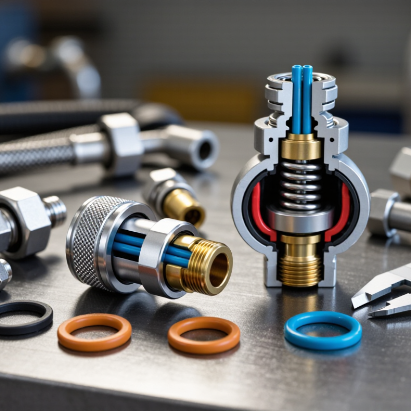
| Body | Provides the pressure boundary and houses the internal components. | The body contains the fluid passage, valve seat, sleeve, locking mechanism, and seal grooves. | Plated carbon steel, stainless steel, brass, or engineered thermoplastics. | Corrosion, thread damage, cracking, or deformation from excessive pressure or impact. | Check for corrosion, dents, damaged threads, and visible leakage around joints. |
| Valves | Control fluid flow and reduce spillage during disconnection. | A valve in each mating half opens when the coupler halves are connected and closes when they are separated. This creates a shut-off function in both halves. | Hardened steel, stainless steel, brass, or polymer valve components. | Valve sticking, incomplete opening, contamination, or leakage after disconnection. | Connect and disconnect at zero or controlled pressure; check for smooth movement and shut-off leakage. |
| Balls | Retain the sleeve or locking ring and hold the mating plug in position. | Multiple hardened balls move into a circumferential groove on the plug. The sleeve prevents the balls from moving outward while the coupler is locked. | Hardened carbon steel, stainless steel, or corrosion-resistant alloy steel. | Pitting, flattening, corrosion, loss of balls, or incomplete engagement in the plug groove. | Inspect the ball track and plug groove; verify that all balls move freely and engage evenly. |
| Sleeve | Controls locking and unlocking of the coupler halves. | Pulling the sleeve back releases the balls for connection or disconnection. Releasing the sleeve allows it to return and cover the balls. | Plated steel, stainless steel, aluminum, or reinforced polymer. | Jamming, bent sleeve, damaged spring, or failure to return to the locked position. | Slide the sleeve through its full travel and confirm automatic return and positive locking. |
| Seals | Prevent fluid leakage between internal parts and at the mating interface. | O-rings, backup rings, and face seals are compressed against machined surfaces to maintain a fluid-tight connection. | Nitrile rubber, fluorocarbon rubber, ethylene propylene rubber, polyurethane, or polytetrafluoroethylene. | Hardening, swelling, cuts, extrusion, chemical attack, or leakage caused by incorrect temperature or fluid compatibility. | Inspect for cuts, flattening, discoloration, and swelling; replace seals during scheduled service. |
| Locking System | Prevents accidental separation under vibration, tension, or pressure. | The locking sleeve, balls, retaining ring, and sometimes a secondary safety device work together to secure the plug in the socket. | Hardened steel, stainless steel, springs, retaining rings, and elastomeric parts. | Incomplete locking, worn grooves, damaged retaining components, or accidental sleeve movement. | Perform a manual pull-check after connection and verify that the sleeve is fully forward and secured. |
| Plug | Provides the mating profile that enters the socket and forms the flow connection. | The plug pushes the valves open and presents a groove or shoulder for the locking balls to engage. | Hardened steel, stainless steel, brass, or compatible engineering plastic. | Scratched sealing surfaces, worn locking groove, incorrect profile, or contamination. | Clean before connection and inspect the nose, sealing surface, and locking groove for damage. |
| Spring and Retainer | Returns moving parts to their normal position and keeps internal components in place. | The spring biases the sleeve or valve toward its resting position, while retainers prevent internal parts from escaping. | Stainless steel, spring steel, carbon steel, or corrosion-resistant alloys. | Spring fatigue, corrosion, breakage, or displaced retaining ring. | Check return force, corrosion, retaining-ring position, and abnormal looseness during service. |