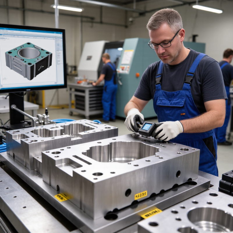
| 1 | Mold base | Rigid, flat support plate sized to the machine platen and mold footprint | Clean the base, remove burrs, and confirm that mounting holes align with the machine layout. | Use a straightedge, feeler gauge, and dimensional inspection of mounting locations. | Uneven support can cause mold deflection, poor thickness distribution, and incomplete forming. |
| 2 | Forming surface | Surface profile matched to the finished part, with smooth transitions and no sharp unintended edges | Install the forming surface or cavity onto the base without forcing or distorting the profile. | Check the profile against the approved CAD model, template, or dimensional drawing. | Incorrect geometry may create wrinkles, webbing, thin corners, or part-release problems. |
| 3 | Draft angles | Often approximately 1° to 3° per side, depending on geometry, texture, and release direction | Confirm that vertical walls include adequate draft before final fastening. | Measure critical walls with an angle gauge or inspect the 3D model and section drawings. | Insufficient draft can lock the part on the mold and damage both the part and the mold surface. |
| 4 | Vacuum channels | Distributed around deep draws, corners, ribs, and other areas where trapped air may remain | Connect channels to the vacuum manifold and keep passages free of chips, sealant, and debris. | Apply low-pressure air or vacuum and confirm flow at all intended outlet locations. | Blocked or poorly positioned channels can cause incomplete detail and air pockets. |
| 5 | Vacuum ports and manifold | Ports sized for the mold volume and connected with short, sealed pathways where practical | Fit ports, hoses, valves, and the manifold; tighten connections without damaging threads. | Perform a leak test and observe vacuum decay after isolating the mold. | Leaks reduce forming speed and may produce uneven replication of the mold surface. |
| 6 | Vent holes | Small openings located at pockets, corners, high points, and deep-draw zones | Drill or install vents according to the design, then deburr the openings on the forming side. | Inspect each vent visually and verify unobstructed airflow from the mold surface. | Oversized vents may leave marks; undersized or blocked vents may trap air. |
| 7 | Heating and cooling provisions | Temperature-control channels or heat-resistant construction appropriate to the forming cycle | Connect cooling lines or confirm heating elements, insulation, and thermal barriers are secure. | Pressure-test fluid channels and check temperature uniformity during a dry run. | Temperature gradients can cause warpage, inconsistent wall thickness, and unstable cycle times. |
| 8 | Parting line and trim reference | Clearly defined line that supports part removal and provides a repeatable trim datum | Align the mold halves or trim features and verify that no unintended step exists at the parting line. | Use a profile gauge, visual inspection, and a sample trim check. | A misaligned parting line can create flash, uneven edges, or difficult downstream trimming. |
| 9 | Locating and fastening hardware | Positive locating features with fasteners suitable for the mold material and expected loads | Install dowels, keys, bolts, washers, and retainers; tighten progressively in a cross pattern. | Check alignment, thread engagement, torque records, and clearance from moving components. | Loose or misaligned hardware may shift the mold, damage threads, or interfere with machine movement. |
| 10 | Release and surface finish | Smooth, clean finish appropriate for the plastic sheet, texture, and required part appearance | Polish or texture approved areas, remove abrasive residue, and apply only a compatible release treatment when required. | Inspect with controlled lighting and compare against the specified surface-finish requirement. | Roughness, contamination, or excess release agent can transfer defects to the formed sheet. |
| 11 | Sensors and reference points | Temperature, pressure, position, or alignment references located where they represent the process accurately | Secure sensors, protect wiring, label connections, and maintain access for calibration. | Confirm signal response, sensor identity, cable routing, and calibration status. | Incorrect sensor placement can cause false process readings and unstable quality. |
| 12 | Final assembly inspection | All components installed, surfaces clean, utilities connected, and safety clearances maintained | Complete a documented inspection before placing the mold into production service. | Use a checklist covering dimensions, vacuum performance, utilities, fasteners, and machine clearance. | Skipping the final inspection increases the likelihood of leaks, collisions, scrap, and unplanned downtime. |