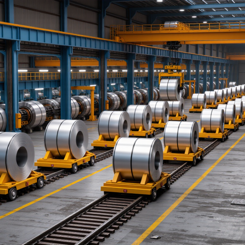
| 1 | Rated load capacity | Specified as a maximum working load; capacity is selected for the actual coil mass and handling arrangement. | The chassis, wheels, drive system, and supporting structure carry the coil and cart during travel. | Confirm the cart rating covers the heaviest coil, any fixture, and the required operating conditions. |
| 2 | Coil support and restraint | A shaped saddle or cradle supports the coil; the required geometry depends on coil diameter, width, and orientation. | The cradle distributes contact forces and helps keep the coil from rolling while the cart moves. | Check coil dimensions, contact surfaces, restraints, and whether the eye is horizontal or vertical. |
| 3 | Travel path | Carts can be designed for rails or for travel on a prepared floor, depending on the application. | Rail-guided wheels follow a fixed route; floor-running carts use steering and wheel systems suited to the site surface. | Assess route length, turns, floor condition, gradients, crossings, and required positioning accuracy. |
| 4 | Power supply | Common options include onboard batteries and site-fed systems such as cable reels or conductor arrangements. | Electrical power drives the traction motors and, where fitted, the controls and auxiliary equipment. | Compare operating distance, charging or supply infrastructure, duty cycle, and maintenance access. |
| 5 | Drive and steering | Drive layout and steering configuration are selected to suit the cart size, load, route, and required maneuverability. | The drive system turns the wheels; steering may be fixed for a straight route or configured to support turning on the site. | Review turning space, wheel loads, travel speed, and whether the route requires straight-line or multidirectional movement. |
| 6 | Loading and unloading interface | The transfer height and support layout must match the crane, forklift, coil car, or production equipment used at each station. | A coil is placed onto or removed from the cart using compatible material-handling equipment or an integrated lifting feature. | Check clearances, alignment, lift points, transfer height, and the sequence of handoffs. |
| 7 | Control method | Control may be operator-driven, remote-controlled, or integrated with site automation, depending on the system design. | Commands regulate starting, stopping, direction, and, where supported, route or position functions. | Confirm operator visibility, communication method, emergency-stop access, and compatibility with plant controls. |
| 8 | Braking and stopping | Braking is designed for the cart’s load, speed, route, and operating environment; the specific arrangement varies by model. | The braking system slows or holds the cart when commanded and may also engage under defined fault conditions. | Request stopping-distance and holding-capability information for the intended load and route. |
| 9 | Safety provisions | Risk controls may include emergency stops, warning devices, guarding, interlocks, and obstacle-detection features where specified. | Safety devices alert people, stop motion, or prevent certain movements when configured conditions are detected. | Evaluate the site risk assessment, pedestrian interaction, visibility, and applicable local requirements. |
| 10 | Duty cycle and maintenance | Service needs depend on operating frequency, environment, power system, wheel and rail conditions, and component design. | Routine inspection helps keep the drive, brakes, wheels, electrical equipment, and coil-support surfaces in working condition. | Ask for the recommended inspection schedule, wear-part list, service access, and expected operating duty. |