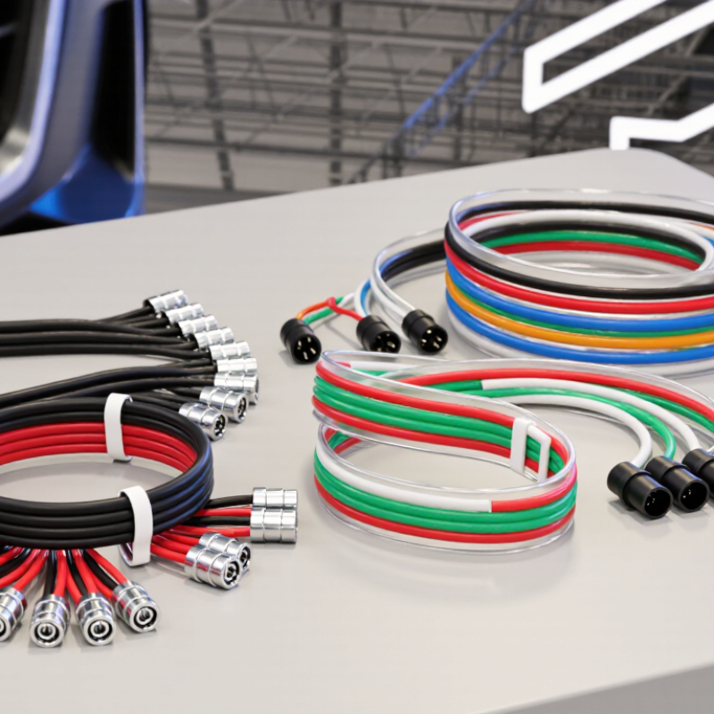
| RGB harness | 4: one common conductor plus R, G, and B channels | Three color channels; the common conductor may be positive or negative, depending on the system. | A PWM controller varies the red, green, and blue channel outputs to create different colors and brightness levels. | Decorative lighting, accent lighting, and color-changing installations. | Confirm the common-wire polarity, connector pinout, voltage, and controller channel layout. |
| RGBW harness | 5: one common conductor plus R, G, B, and W channels | Four independently controlled channels; the white channel is separate from RGB. | PWM adjusts the RGB channels for color and the dedicated white channel for white-light output or blended effects. | Installations needing both saturated colors and a dedicated white-light mode. | Use a four-channel RGBW controller and verify that the white-channel pin matches the harness and light. |
| RGB extension harness | Usually 4, matching the connected RGB system | Carries the common connection and three RGB channels between compatible components. | Does not create colors itself; it carries the controller’s channel signals and power connections. | Extending the distance between an RGB controller and light sections. | Match conductor count, pin order, connector type, and electrical ratings; account for voltage drop on longer runs. |
| RGBW extension harness | Usually 5, matching the connected RGBW system | Carries the common connection plus four RGBW channels. | Passes separate PWM-controlled RGB and white-channel connections through the extension. | Extending RGBW light runs while retaining independent white-channel control. | Check the five-pin wiring order and extension rating; do not assume RGB and RGBW pinouts are interchangeable. |