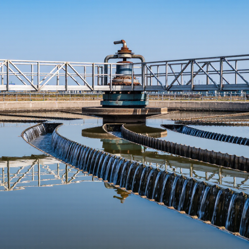
| Thickener Tank | Circular steel or concrete tank with a shallow conical or sloped floor; industrial diameters commonly range from several metres to more than 100 metres. | Provides the settling volume in which suspended solids separate from water by gravity. | Tank diameter, depth, feed solids concentration, particle settling rate, and required overflow clarity determine the effective capacity. |
| Peripheral Drive Mechanism | Drive location: tank rim
Usually consists of a motor, gearbox, pinion, and wheel or rail arrangement. | Moves the bridge or rotating structure around the tank perimeter while transmitting torque to the rake assembly. | Peripheral driving is well suited to large-diameter tanks because the drive load is distributed around the circumference rather than concentrated at a central shaft. |
| Rotating Bridge or Traveling Structure | Steel bridge, truss, or support frame spanning the tank and connected to the peripheral drive. | Supports and transports the rake arms, feedwell components, scraper equipment, and access platforms. | Structural stiffness, wheel alignment, corrosion protection, and safe access are important for reliable continuous operation. |
| Rake Arms and Rake Blades | Radial arms fitted with inclined blades or pickets; rotational speed is commonly slow, often measured in revolutions per hour rather than revolutions per minute. | Gently gathers settled solids toward the central underflow discharge point and releases trapped water from the sludge bed. | Excessive speed can disturb the settled bed and increase torque demand; insufficient movement may allow solids accumulation or uneven bed formation. |
| Feedwell | Central cylindrical or flocculation-style chamber positioned below the feed inlet. | Receives incoming slurry and dissipates its momentum before distributing the feed into the settling zone. | A well-designed feedwell reduces turbulence, protects flocs from shear, and promotes even radial flow across the tank. |
| Feed Pipe and Inlet Assembly | Pipework that introduces dilute slurry to the central feedwell, often with a submerged or controlled-discharge arrangement. | Transfers process slurry into the thickener while limiting short-circuiting and surface disturbance. | Feed flow rate, inlet velocity, pipe diameter, and elevation should be selected to avoid excessive turbulence and air entrainment. |
| Flocculant Addition System | May include polymer preparation, aging, dilution, metering pumps, and injection points upstream of or within the feedwell. | Promotes particle agglomeration, increasing effective settling velocity and improving solids capture. | Polymer type and dose depend on ore or process chemistry, particle size, pH, temperature, and feed solids concentration. Overdosing can increase cost and may impair performance. |
| Settling Zone | Relatively quiescent tank volume between the feedwell and the clarified-water surface. | Allows flocculated solids to settle while clarified liquid rises toward the overflow launder. | Hydraulic loading, solids flux, particle settling characteristics, and short-circuiting control the required area and performance. |
| Sludge Bed | Concentrated layer of settled solids accumulated above the tank floor. | Provides compression and drainage, increasing underflow solids concentration beyond the concentration achieved by free settling alone. | Bed depth and density must be controlled. Excessive bed buildup can cause high rake torque, bogging, or unstable underflow discharge. |
| Underflow Cone and Discharge Pipe | Central floor cone connected to an underflow outlet, pump, or controlled discharge valve. | Collects and removes thickened solids from the tank. | Underflow withdrawal should be matched to solids feed and bed inventory. Poor control may cause dilution, blockage, or excessive bed accumulation. |
| Overflow Launder | Peripheral channel, often fitted with a serrated or notched weir for level control. | Collects clarified water evenly around the tank perimeter and directs it to the overflow outlet. | Levelness, weir loading, launder cleanliness, and hydraulic balance influence overflow clarity and reduce localized carryover. |
| Torque Measurement and Protection | Torque sensor, overload relay, shear pin, hydraulic protection, or automatic lift mechanism, depending on the design. | Detects increasing resistance from dense sludge, solids accumulation, or mechanical problems. | High torque should trigger an operator response or automatic protective action before structural or drive-system damage occurs. |
| Drive Speed | Very low rotational speed selected to move settled solids without resuspending them; the exact value depends on tank diameter and rake design. | Balances solids transport, bed disturbance, torque demand, and residence time. | Drive speed should be evaluated together with rake geometry, solids characteristics, underflow rate, and flocculant performance rather than treated as an isolated setting. |
| Overflow Solids Concentration | Normally targeted to remain low relative to the feed, although the actual value depends on feed characteristics and process requirements. | Indicates the effectiveness of particle capture and clarification. | Rising overflow solids may indicate excessive hydraulic loading, inadequate flocculation, feedwell turbulence, short-circuiting, or an overloaded solids bed. |
| Underflow Solids Concentration | Varies widely by material and process; commonly controlled through bed inventory, rake operation, dilution-water management, and pumping rate. | Represents the concentration of thickened solids leaving the unit. | Higher concentration can reduce downstream water load, but excessively dense underflow may increase pumping difficulty and rake torque. |