| Pump type and function | Confirm the replacement uses the same pump principle and performs the same circuit function, such as supplying a hydraulic system or serving a dedicated control circuit. | Compare the equipment documentation, circuit diagram, and existing pump identification plate. | The replacement is suitable for the same duty and circuit arrangement. |
| Displacement and flow | Check displacement in cm³/rev and required flow in L/min. For a fixed-displacement pump, theoretical flow is displacement × rotational speed; actual flow is lower because of internal leakage and operating conditions. | Compare the rated displacement and the system’s required flow at the specified operating speed. Confirm the manufacturer’s performance data for the intended pressure and fluid. | Flow capacity meets the machine requirement without exceeding the drive or system limits. |
| Pressure rating | Check continuous, intermittent, and peak pressure ratings separately; these ratings are not interchangeable. | Compare the pump’s published ratings with the system operating pressure and pressure-relief setting. | The pump is rated for the system’s intended duty and pressure peaks. |
| Rotational speed and direction | Verify the permitted speed range and required direction of rotation, viewed from the specified shaft end. | Check the drive motor or engine speed, the pump documentation, and any rotation marking on the unit. | The drive speed and rotation direction are within the pump’s limits and match the circuit requirement. |
| Shaft and coupling | Compare shaft diameter, length, profile, key or spline details, and coupling engagement. | Measure the existing drive interface and check the replacement drawing. Do not force a coupling onto a mismatched shaft. | The shaft and coupling mate correctly and transmit the required torque without binding. |
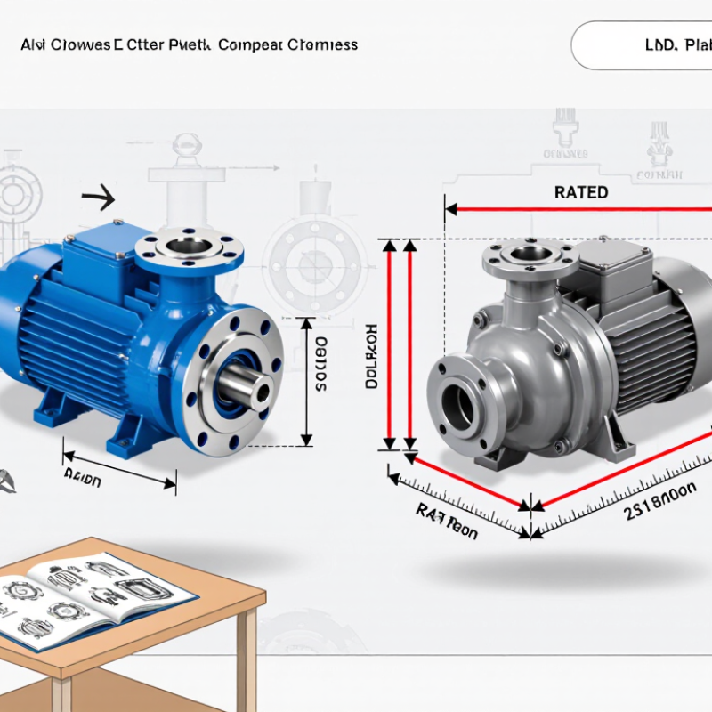
| Mounting and envelope | Check mounting face, bolt pattern, pilot diameter, overall dimensions, and clearance around the installed pump. | Compare dimensional drawings and measure the mounting area before installation. | The pump mounts securely, aligns with the drive, and clears nearby components. |
| Port type, size, and position | Confirm inlet and outlet port locations, thread or flange standard, nominal size, and connection orientation. | Check the port drawing and identify the actual connection standard; similar-looking threads may not seal correctly together. | Connections match the hoses or manifolds and can be installed without cross-threading or harmful line strain. |
| Hydraulic fluid and temperature | Check fluid type, viscosity range, cleanliness requirements, and permitted operating temperature. | Compare the pump documentation with the fluid specification and expected cold-start and operating temperatures. | The fluid and operating conditions fall within the pump’s published limits. |
| Controls and auxiliary features | Check whether the pump is fixed or variable displacement and whether it includes compensators, control ports, sensors, or other required features. | Compare the control schematic and connection details with the machine circuit. | Control behavior and auxiliary connections support the original system function. |
| Pre-start and commissioning checks | Check cleanliness, correct fluid level, secure fittings, correct rotation, and proper pump priming where required by the manufacturer. | Follow the pump and machine service instructions. Start at low load and monitor pressure, flow, temperature, noise, and leakage. | Measured operation is stable and within the equipment’s specified limits before returning the machine to service. |