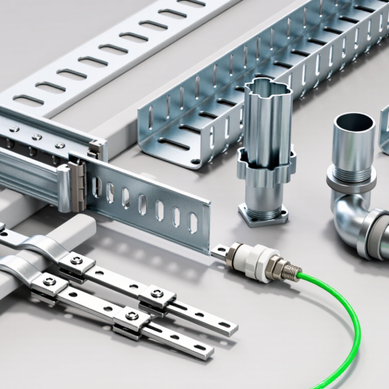
| Straight splice connector | Joins two tray sections in a continuous straight run. | Normally provides a fixed connection; it is not intended to serve as a thermal expansion joint. | Routine straight runs where significant relative movement is not required at the joint. | Use the connector type and fasteners specified for the tray system. Do not substitute a standard splice for an expansion connection where thermal movement is expected. |
| Expansion splice connector | Joins tray sections while allowing controlled longitudinal movement. | Allows the tray ends to move relative to one another as temperature changes. | Long runs, outdoor installations, and locations subject to substantial temperature variation. | Determine joint locations and the installation gap from the applicable NEMA VE 2 guidance and the tray system manufacturer’s instructions. Set the gap for the expected temperature range and the temperature at installation. |
| Flexible connector | Connects tray sections where limited flexing or relative movement is needed. | Accommodates flexing or movement within the connector’s intended limits; it is not automatically a substitute for a designed expansion joint. | Transitions or locations where vibration, alignment variation, or localized movement is a design consideration. | Confirm the connector’s permitted movement, load capacity, bonding requirements, and suitability for the specific tray material and installation. |
| Horizontal adjustable splice connector | Connects sections through a horizontal direction change or alignment adjustment. | Provides adjustment for routing and fit-up; it is not generally designed to accommodate long-run thermal expansion. | Horizontal bends or field-adjusted tray routes. | Check that the completed joint maintains the required mechanical support and electrical continuity for the installation. |
| Vertical adjustable splice connector | Connects sections through a vertical direction change or elevation adjustment. | Provides adjustment for elevation and routing; it is not generally an expansion joint. | Vertical bends, risers, or changes in tray elevation. | Follow the tray system’s installation instructions and support requirements at the change in direction. |
| Bonding or grounding jumper | Provides electrical bonding across a joint where required by the design or applicable electrical rules. | Can preserve electrical continuity while allowing movement when a suitable flexible jumper is used. | Expansion joints or other joints where electrical continuity must be maintained. | Use a jumper suitable for the expected movement and environmental conditions. A jumper does not replace the mechanical expansion connector. |