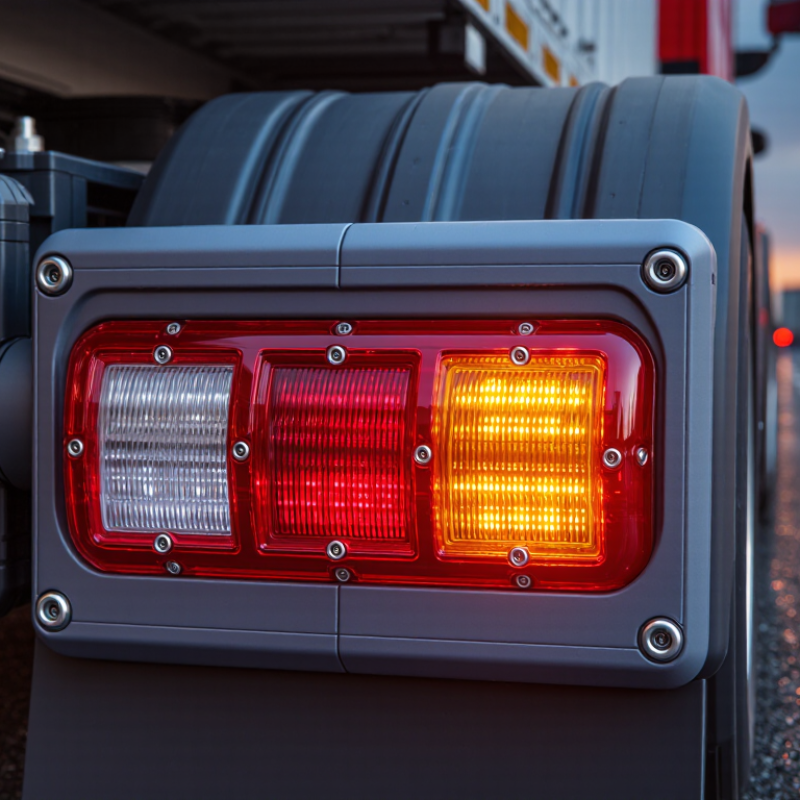
| Lighting Functions | Stop, turn indicator, and rear position or tail-light requirements | One LED assembly may combine several functions, but each function must provide the required color, intensity, visibility, and separation from other lamps. | Confirm that the product is designed for the intended vehicle category and that the functions comply with the destination market’s lighting rules. |
| North American Compliance | FMVSS No. 108; SAE J585 for stop lamps; SAE J588 for turn signal lamps | Vehicles and lamps supplied for the United States or Canada may need photometric performance, mounting, visibility, color, and identification requirements specified by applicable regulations. | Do not rely only on a general “DOT compliant” statement. Request applicable test evidence and verify whether the complete vehicle installation remains compliant. |
| European and UNECE Compliance | UNECE Regulation No. 6 for direction indicators; UNECE Regulation No. 7 for front and rear position lamps, stop lamps, and end-outline marker lamps | Approved lamps generally require the appropriate approval marking and must meet prescribed photometric and installation conditions. | For European-market supply, check the exact UNECE function approval rather than assuming that an approval for one lamp function covers all functions in a combination lamp. |
| Other Market Rules | National or regional vehicle-lighting regulations | Australia, Japan, the Gulf region, South America, and other markets may apply local rules, adopted UNECE requirements, or modified national requirements. | Identify the destination country before finalizing the design, markings, test plan, and mounting instructions. |
| Electrical Voltage | Vehicle electrical-system specification | Passenger vehicles commonly use nominal 12 V systems, while many commercial vehicles use nominal 24 V systems. Actual operating voltage is higher or lower during charging, starting, and transient events. | Verify the lamp’s rated operating range and transient protection. A 12 V-only product should not be connected to a 24 V system without an approved voltage-conversion solution. |
| Current Draw and Load Compatibility | Vehicle circuit design and lamp-monitoring strategy | LED lamps normally draw less current than incandescent lamps. Some vehicles may interpret the lower load as a failed bulb and generate a warning or rapid-flash condition. | Check whether a load resistor, electronic flasher, decoder, or vehicle configuration is required. Resistors can create heat and should be installed according to safety instructions. |
| CAN Bus and Electronic Control | Vehicle body-control module and bulb-failure monitoring system | Modern vehicles may monitor lamp current, pulse-width modulation, open circuits, short circuits, and communication-related faults. | Confirm compatibility with the vehicle’s control architecture before purchase. A lamp that works on a simple circuit may require additional engineering on a networked vehicle. |
| Connector and Wiring | Vehicle-specific connector, pinout, and harness design | Common differences include connector shape, number of pins, pin assignment, ground location, wire polarity, and combined or separate stop-turn circuits. | Request the connector drawing and pinout. A mechanically compatible plug does not guarantee electrically compatible function allocation. |
| Polarity and Grounding | Vehicle wiring architecture | Most automotive LED assemblies require correct positive and ground connections. Some installations use a shared ground, while others use separately controlled circuits. | Verify positive and negative terminals, shared-ground requirements, and whether the lamp is suitable for positive-ground or negative-ground systems. |
| Light Color | Applicable regional lighting regulation and photometric test method | Stop and tail functions are generally red. Rear direction indicators may be red or amber depending on the market and vehicle configuration. | Choose the correct lens and LED color for the destination market. A visually acceptable color may still fail the required chromaticity range. |
| Photometric Performance | Applicable FMVSS, UNECE, national, or technical standard | Compliance can depend on luminous intensity, illuminated area, vertical and horizontal angles, uniformity, and separation between functions. | Ask for test results covering the complete lamp and intended mounting orientation, not only a bare LED or laboratory sample. |
| Visibility and Mounting Position | Destination-market installation requirements | Required mounting height, spacing, geometric visibility, lamp separation, and orientation vary by vehicle type and jurisdiction. | Check the installation envelope and mounting instructions. A compliant lamp can become non-compliant when installed at an incorrect height, angle, or spacing. |
| Ingress Protection | IEC 60529 IP Code | IP ratings classify protection against solid objects and water under defined laboratory conditions. They do not by themselves certify vehicle-lighting compliance. | Use an appropriate IP level for the location, such as exposed rear bodywork or trailer service. Also review sealing, pressure equalization, connector protection, and drainage design. |
| Environmental Durability | Automotive environmental and vibration test specifications | Rear lamps may experience vibration, thermal cycling, humidity, salt spray, dust, car-wash exposure, and road chemicals. | Request evidence of environmental testing suitable for the intended vehicle application. Housing material, lens sealing, PCB coating, and thermal design all affect service life. |
| Thermal Management | LED junction-temperature and housing design principles | LED efficiency reduces energy use, but heat generated by LEDs and electronic drivers still needs to be transferred away from the junction and control components. | Check the specified operating-temperature range, heat-sink or housing design, and performance after thermal aging to reduce premature dimming or failure. |
| Response Time | Applicable stop-lamp and turn-signal performance requirements | LEDs reach operating brightness faster than incandescent filaments, although the complete driver circuit still determines the actual switching behavior. | Faster illumination can support clear driver communication, but the product should still be evaluated against the response-time requirements of the destination market. |
| Service Life and Maintenance | Rated life under defined temperature, voltage, and duty-cycle conditions | LED assemblies generally avoid filament burnout and can offer long service life, but drivers, seals, solder joints, and thermal interfaces can still fail. | Compare the test conditions behind life claims. Confirm whether the assembly is replaceable, repairable, or supplied as a sealed unit. |
| Trailer and Commercial-Vehicle Use | Trailer wiring standards, vehicle regulations, and 12 V or 24 V system requirements | Trailers and heavy vehicles may use different voltage systems, long harnesses, multiplex wiring, and separate stop and turn circuits. | Confirm voltage, connector type, circuit allocation, cable length, and compatibility with trailer monitoring modules before fleet deployment. |
| Approval Markings and Documentation | Destination-market certification and marking requirements | Markings may identify approved functions, category, voltage, approval number, or other regulatory information. The exact format depends on the jurisdiction. | Request drawings, label photographs, declarations, test reports, installation instructions, and change-control information before importing at scale. |
| Interchangeability | Original lamp dimensions and vehicle mounting interface | Matching the external shape alone is insufficient. Hole spacing, lens clearance, gasket profile, flange depth, cable exit, and lamp orientation also affect fitment. | Use dimensional drawings and a sample-fit inspection to prevent water ingress, body interference, loose mounting, or incorrect beam orientation. |
| Purchase Verification Checklist | Technical data sheet, sample test, and destination-market review | Verify voltage range, current draw, pinout, functions, color, approval scope, IP rating, temperature range, dimensions, and installation orientation. | A structured pre-purchase check reduces compatibility failures, customs delays, warranty claims, and non-compliant vehicle installations. |