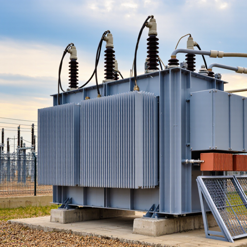
| Definition | A power transformer designed for medium-voltage systems with a nominal voltage of approximately 35 kV. | It transfers electrical energy between voltage levels while maintaining the same frequency. |
| Common Equipment Voltage Class | 40.5 kV maximum system-voltage class is commonly used for equipment connected to 35 kV networks. | The higher equipment rating provides insulation and operating margin above the nominal network voltage. |
| Typical Voltage Ratio | Examples include 35/10 kV, 35/6.3 kV, 35/0.4 kV, and 35/11 kV, depending on the distribution system. | The ratio is selected to match the utility network, industrial load, or renewable-energy collection system. |
| Typical Rated Power | Common project ratings range from about 1 MVA to 63 MVA; larger ratings may be available for specific substations. | The required MVA rating should account for present demand, motor starting, harmonics, and planned load growth. |
| Frequency | 50 Hz or 60 Hz, according to the local power system. | Frequency affects the magnetic design, losses, impedance, and compatibility with the connected network. |
| Transformer Type | Oil-immersed transformers are common for outdoor substations; cast-resin or dry-type designs are used where fire safety or indoor installation is important. | The construction type influences fire risk, maintenance, installation space, environmental protection, and total cost. |
| Cooling Method | ONAN cooling is widely used for oil-immersed units; larger transformers may use ONAF cooling with fans. | Cooling capacity determines the continuous load capability and helps control insulation aging. |
| Tap-Changer Arrangement | An off-circuit tap changer is common; an on-load tap changer may be specified when voltage regulation is required during operation. | Tap adjustment helps compensate for network-voltage variation and maintain an appropriate secondary voltage. |
| Typical Applications | Utility distribution substations, industrial plants, mining sites, commercial facilities, data centers, and renewable-energy collection networks. | A 35 kV level is suitable for delivering substantial power over medium distances with lower current than low-voltage distribution. |
| Transmission Efficiency | For the same transferred power, increasing voltage reduces current and therefore lowers conductor I²R losses. | This can improve feeder efficiency and reduce the required conductor size compared with lower-voltage distribution. |
| Insulation Requirements | The design includes phase-to-ground and phase-to-phase insulation suitable for the applicable 35 kV system and overvoltage conditions. | Adequate insulation coordination protects the transformer against switching surges, lightning impulses, and temporary overvoltages. |
| Protection and Monitoring | Typical devices include overcurrent and earth-fault protection, temperature monitoring, pressure relief, and, for oil-filled units, gas or oil-level monitoring. | Protection systems detect abnormal conditions quickly and help limit equipment damage and service interruptions. |
| Applicable Standards | Design and testing commonly reference IEC 60076 or equivalent national standards, together with local grid requirements. | Standards define requirements for ratings, insulation, temperature rise, losses, routine tests, and type or special tests. |
| Primary Selection Factors | Load profile, rated power, voltage ratio, short-circuit impedance, installation environment, cooling method, tap range, and future expansion. | Correct specification improves reliability, energy efficiency, safety, maintainability, and lifecycle cost. |