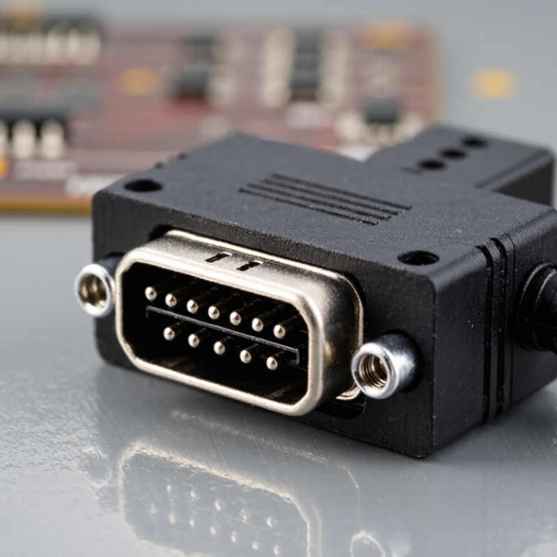
| Contact Arrangement | Confirm four electrical contacts, female terminal orientation, keying, pin numbering, and mating direction. | Pin numbering and mechanical keying must match the mating half and cable drawing with no ambiguity. | Prevents incorrect mating, reversed signals, and costly tooling or cable changes. | Dimensioned drawing, 2D pinout, 3D CAD file, and first-article sample. |
| Electrical Rating | Check rated voltage, rated current, contact resistance, insulation resistance, and dielectric withstand voltage. | The connector rating should exceed the application load with an engineering safety margin; contact resistance should remain stable after testing. | Electrical ratings vary with wire size, temperature, spacing, housing material, and circuit conditions. | Product specification, test conditions, electrical test report, and derating curve. |
| Current-Carrying Capability | Evaluate conductor size, number of energized circuits, ambient temperature, and allowable temperature rise. | Use the manufacturer’s current-versus-temperature curve rather than relying only on a nominal current value. | Four contacts in a small housing can experience thermal derating when all circuits operate simultaneously. | Temperature-rise report, derating chart, and application-specific validation data. |
| Mating Compatibility | Verify mating cycles, insertion force, withdrawal force, terminal retention, and prevention of partial mating. | Mating performance should remain within the specified limits after the stated cycle test. | Helps protect field-service reliability and reduces intermittent connection failures. | Mating-cycle procedure, force measurements, terminal-retention results, and inspection records. |
| Mechanical Fit | Check housing dimensions, panel cut-out, mounting method, cable exit, strain relief, and clearance around the connector. | Critical dimensions should be controlled by drawing tolerances and verified with calibrated gauges or measuring equipment. | Dimensional differences between suppliers can prevent direct interchangeability. | Controlled drawing, tolerance table, inspection report, and approved golden sample. |
| Environmental Protection | Identify required ingress protection, operating temperature, humidity, vibration, shock, and corrosion resistance. | Select an IP rating only when the complete mated assembly, seals, cable, and installation method have been tested together. | An unsealed connector may be unsuitable for outdoor, wet, dusty, or washdown environments. | Environmental test reports, seal material information, and installation instructions. |
| Materials and Plating | Review contact alloy, plating system, housing resin, terminal base material, and compatibility with the mating contact. | Materials should be traceable and suitable for the expected current, temperature, humidity, and corrosion exposure. | Material selection affects conductivity, wear resistance, oxidation behavior, and long-term contact stability. | Material declarations, plating-thickness report, resin datasheet, and batch traceability. |
| Safety and Flammability | Confirm housing flammability performance, insulation design, creepage, clearance, and protection against accidental contact. | The design should satisfy the applicable end-product safety requirements for the intended voltage and environment. | Safety requirements differ by product category and destination market; a generic claim may not be sufficient. | Flammability report, safety file, insulation test results, and product risk assessment. |
| Regulatory Compliance | Check restricted substances, material declarations, recycling obligations, and destination-market documentation requirements. | Obtain current declarations for applicable RoHS and REACH requirements and verify that they cover all supplied materials. | Incomplete declarations can delay customs clearance, customer approval, or market release. | Signed compliance declaration, substance report, supplier material list, and revision-controlled records. |
| Quality Control | Evaluate incoming-material inspection, in-process controls, terminal crimp checks, visual inspection, and final electrical testing. | Critical characteristics should have documented control limits, sampling plans, and nonconformance procedures. | Consistent process control is more reliable than approval based on a single sample. | Control plan, process-flow diagram, inspection records, capability data, and corrective-action history. |
| Cable Termination | Confirm wire gauge range, insulation diameter, stripping length, crimp geometry, pull force, and tooling requirements. | Crimp dimensions and pull-force results should meet the terminal specification for every approved wire combination. | Poor crimp control can create high resistance, conductor damage, or intermittent field faults. | Crimp application specification, cross-section analysis, pull-force test, and approved tooling list. |
| Supply Continuity | Review capacity, lead time, minimum order quantity, tooling ownership, alternate materials, and change-notification policy. | The sourcing plan should include forecast visibility, safety stock rules, and formal approval for changes affecting fit, form, or function. | A technically suitable connector can still create risk if supply interruptions or uncontrolled changes occur. | Capacity statement, lead-time history, business-continuity plan, and change-control agreement. |
| Packaging and Identification | Check terminal protection, moisture control, lot coding, quantity accuracy, labeling language, and barcode requirements. | Packaging must prevent deformation, contamination, corrosion, and mixing of different revisions or pin configurations. | Clear identification supports warehouse control, traceability, and efficient receiving inspection across regions. | Packaging specification, label sample, lot-traceability format, and shipment inspection checklist. |