| Overlay Composition | Iron–chromium–carbon alloy; some grades also contain manganese, molybdenum, niobium, or other alloying elements. | Chromium-rich primary carbides, mainly chromium carbide, form in a hard wear-resistant matrix. | Use a standard Fe–Cr–C overlay for general sliding and low-to-moderate impact wear. Consider alloy-modified grades when elevated temperature, severe abrasion, or impact is expected. | The exact chemistry should be checked against the supplier’s mill certificate or product data sheet because performance varies by welding process and formulation. |
| Overlay Hardness | Commonly about 55–65 HRC, or approximately 550–800 HV, depending on alloy and test method. | Higher hardness generally improves resistance to cutting and sliding abrasion, but it does not automatically provide better resistance to heavy impact. | Prioritize hardness for dry, abrasive contact. For high-impact service, select a balanced matrix and verify impact resistance instead of choosing solely by the highest hardness value. | Hardness values measured by different scales or locations are not always directly comparable. Confirm the testing standard and measurement position. |
| Carbide Volume Fraction | Typically around 30–50% by volume in many commercial Fe–Cr–C overlays; the actual value varies by product. | A higher carbide fraction can improve abrasion resistance, while matrix continuity influences toughness and crack behavior. | Select a higher carbide fraction for severe sliding abrasion and a more ductile matrix for combined abrasion and impact. | Carbide size, morphology, distribution, and orientation are as important as the percentage alone. |
| Wear Mechanism | Sliding abrasion, gouging abrasion, erosion, or combined abrasion and impact. | Different wear mechanisms place different demands on the carbide network and supporting steel substrate. | For fine-particle sliding abrasion, use a uniform, hard overlay. For large rocks or severe impact, use a tougher overlay or a different wear-resistant alloy if necessary. | Describe the feed material, particle size, moisture, impact height, and operating temperature before final selection. |
| Typical Plate Thickness | Common total thicknesses are approximately 4–25 mm, including the base plate and overlay, although wider ranges are available. | Thickness affects service life, structural stiffness, weight, and fit-up. | Choose thickness according to expected wear allowance, component geometry, load, and available clearance. Avoid adding thickness that interferes with material flow or equipment movement. | Specify base thickness and overlay thickness separately when dimensional accuracy is important. |
| Base Plate Material | Usually a weldable carbon steel or low-alloy steel substrate. | The substrate provides structural support and allows the overlay plate to be welded, bolted, or mechanically attached. | Confirm the base steel grade, yield strength, weldability, and required forming method before fabrication. | The base plate should remain sufficiently ductile for handling and installation even though the overlay surface is hard and relatively brittle. |
| Operating Temperature | Many conventional Fe–Cr–C overlays are used at temperatures below approximately 500–600°C, subject to the alloy and service conditions. | Heat can reduce matrix strength, change residual stresses, and accelerate oxidation or distortion. | For continuous high-temperature service, request temperature-specific data and consider an alloy designed for heat and oxidation resistance. | Do not use a general room-temperature hardness value as proof of performance at elevated temperature. |
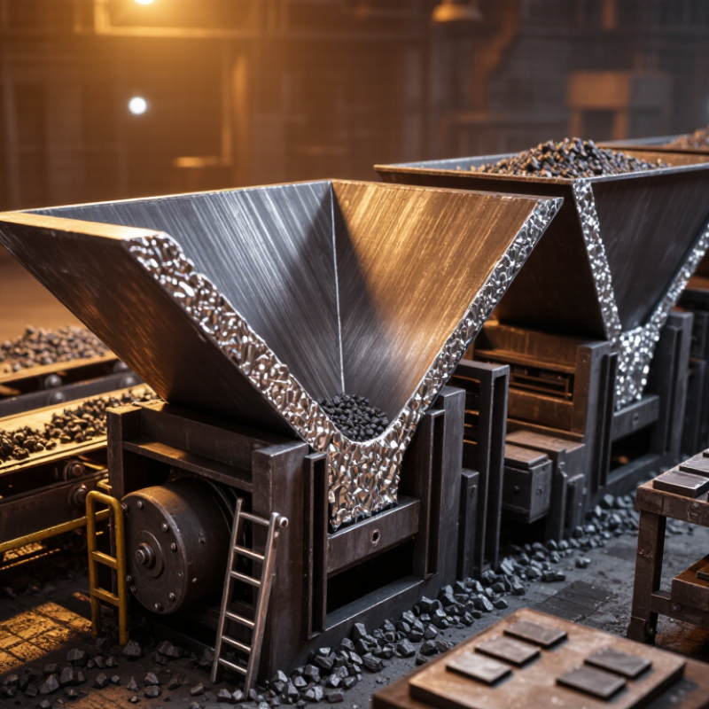
| Plate Surface Condition | Overlay surfaces commonly contain transverse stress-relief cracks; crack spacing and pattern depend on plate thickness and welding procedure. | These cracks help release residual welding stress and do not necessarily indicate premature failure. | Accept cracks only within the agreed technical specification. Reject plates with excessive delamination, lack of fusion, or cracks extending through the base plate. | Crack acceptance criteria should be defined before purchase and supported by visual inspection and, when required, non-destructive testing. |
| Fabrication Method | Cutting, drilling, bending, bolting, countersinking, and welding are possible with suitable procedures. | The hard overlay is more difficult to machine than ordinary carbon steel and can damage conventional tools. | Use plasma or abrasive cutting where appropriate. Prefer drilling from the base-steel side with carbide tools or specialized equipment. | Leave an unoverlaid edge, mounting holes, or machined areas when the design requires easy fabrication or welding. |
| Bending and Forming | Cold forming is limited and depends on overlay thickness, crack pattern, radius, and base-plate ductility. | Excessive forming strain may cause overlay cracking, spalling, or distortion. | Use a larger bend radius and form with the overlay on the outside only when permitted by the technical specification. Order preformed sections for complex shapes. | Trial forming should be performed on a representative sample before production fabrication. |
| Joining and Welding | Welding is normally performed from the base-steel side or on designated unoverlaid edges using a compatible procedure. | Heat input, preheating, interpass temperature, and filler selection affect cracking and distortion. | Follow a qualified welding procedure based on the base steel and service requirements. Avoid welding directly onto the hard overlay unless specifically permitted. | Low-hydrogen consumables, controlled heat input, and gradual cooling may be required for thicker or higher-carbon substrates. |
| Installation Orientation | Install the carbide overlay toward the material flow or wear source. | The exposed overlay must directly receive the abrasive action; the base steel is intended to provide support. | For sliding chutes and liners, orient the overlay to minimize impact angles and material hang-up. For impact zones, use a design that distributes load. | Use countersunk fasteners, plug welds through prepared holes, or perimeter welds where suitable for the equipment design. |
| Main Applications | Chutes, hoppers, transfer points, screens, crusher liners, mixing blades, wear bars, and material-handling equipment. | These components commonly experience abrasive contact from minerals, coal, cement raw materials, sand, or other bulk solids. | Match the overlay grade and thickness to the specific material, flow rate, particle size, impact energy, and expected maintenance interval. | Use wear mapping or thickness measurements during service to identify high-wear zones and optimize liner layout. |
| Quality Verification | Typical checks include dimensions, visual condition, overlay thickness, hardness, chemistry, base-metal properties, and weld quality. | Inspection confirms that the supplied plate matches the agreed technical requirements. | Specify inspection standards, sampling frequency, test locations, dimensional tolerances, and documentation requirements in the purchase specification. | A representative sample or test coupon can be useful for confirming hardness, microstructure, and bond quality before large-scale production. |
| Service-Life Evaluation | Actual life depends on abrasive hardness, particle size, impact, temperature, material flow, plate thickness, and installation quality. | Laboratory abrasion results may not reproduce the complete field environment. | Compare candidates using field wear rate, maintenance hours, replacement frequency, and total installed cost—not only initial price. | Record plate thickness at installation and during maintenance to support data-based future selection. |
| Cost Consideration | Evaluate material price, fabrication, transport, installation, downtime, replacement labor, and expected service life. | A more expensive plate may provide lower total cost if it extends maintenance intervals and reduces production interruptions. | Use total cost of ownership and wear rate per operating hour when comparing different plate specifications. | Supplier location may affect lead time and logistics cost, but technical compliance and consistent quality should remain primary criteria. |