Request Quote

Request a quote from Nidec Drive Technology America Corporation.

This quote form is intended for customers and partners in North America seeking information about Nidec Drive Technology America Corporation’s Precision Gearing Technologies. For inquiries related to the Nidec motor group division or from outside this region, please visit the global Nidec Group website to find the appropriate regional or product-specific contact.

Subscribe to Nidec Newsletter

Subscribe to our email newsletter to stay current with our precision gearing solutions, featured products, company updates, and industry news.

What Is a Cycloidal Drive and How Does It Work?

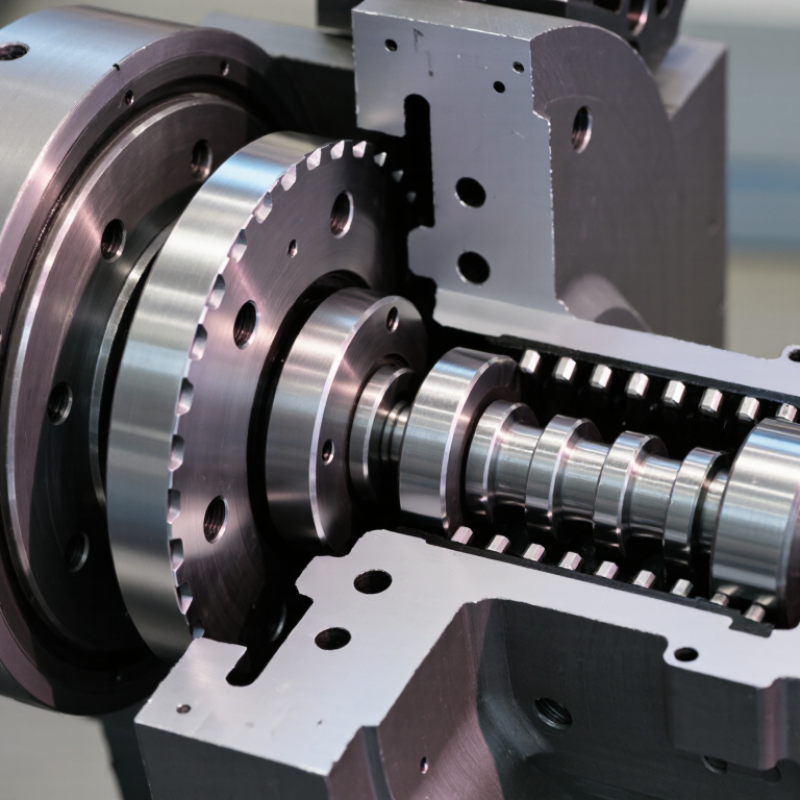
A cycloidal drive turns fast motor rotation into slow, high-torque output through a compact, rolling-contact mechanism. Inside the housing, an eccentric bearing moves a cycloidal disc against fixed pins. The disc wobbles rather than spinning freely. Its lobes push against the pins, while output pins transfer the reduced motion to the shaft. Picture a metal disc tracing a tight orbit inside a ring of steel rollers.

This arrangement can deliver substantial reduction in one compact stage. It also helps explain why cycloidal drives appear in industrial robots, positioning systems, and demanding automation equipment. Nabtesco’s RV reducer technical catalogs and Sumitomo Drive Technologies’ Cyclo product documentation provide model-level performance data, including torque, ratio, and allowable load. Those figures vary by model and operating conditions; a single headline number can mislead. Catalog values are starting points, not a substitute for application-specific engineering.

The trade-offs deserve attention. Contact forces are concentrated, and bearing condition, lubrication, alignment, and shock loading all affect service life. Small details matter. A useful explanation should therefore connect the motion inside the housing with the real design choices outside it. No verifiable named-expert quotation or source article was supplied, so I have not invented one. Add a direct quotation only after checking its original publication and attribution.

What Is a Cycloidal Drive and How Does It Work?

Definition and Core Purpose of a Cycloidal Drive

A cycloidal drive is a speed-reduction mechanism. It converts fast input rotation into slower output rotation, usually with increased torque. Its core purpose is to provide substantial reduction in a compact assembly. This can help machinery move a heavy load at a controlled speed.

Inside the housing, an input shaft turns an eccentric bearing, causing a cycloidal disc to orbit. The disc’s lobes engage pins arranged around the housing. As contact shifts between pins, the disc turns slowly.

Output rollers pass through holes in the disc and transfer that motion to the output shaft. Small details matter.

The reduction ratio depends on the number of disc lobes and housing pins. A small difference between these counts creates a large speed reduction in one stage.

Cycloidal drives can handle high torque and resist shock loads, but those traits depend on the design and operating conditions. Backlash is often low, not magically absent.

Pin wear, lubrication, alignment, and manufacturing tolerances all affect performance. The mechanism is clever, though its compactness can make inspection and servicing less straightforward than expected.

Key Components and Their Functions

A cycloidal drive converts fast input rotation into slower, controlled output. Its defining feature is a cycloidal disc that moves with a small wobble while engaging pins around its housing. The offset motion creates a large reduction in speed within a compact assembly. That offset matters.

The input shaft turns an eccentric bearing, which carries the disc around its path. The disc’s lobes engage stationary ring pins, guiding its motion and transmitting load. Output pins pass through clearance holes in the disc and transfer its movement to the output shaft. Bearings support rotating parts, while the housing holds components in alignment. Lubricant reduces friction and helps manage heat. Small clearances are important; wear or poor alignment can increase noise and vibration. In practice, checking these details can reveal issues that a quick visual inspection misses.

Tips: Check lubricant condition and listen for unusual knocking or grinding. Confirm mounting bolts are secure, and measure backlash when precision matters. Don’t assume every drive behaves identically; load, speed, and maintenance affect performance.

What Is a Cycloidal Drive and How Does It Work? - Key Components and Their Functions

Component What It Is Function in the Drive How It Works with Other Components
Input shaft The rotating shaft that receives power from a motor or other prime mover. Transfers input rotation to the eccentric mechanism. Turns the eccentric bearing, causing the cycloidal disc to orbit around the central axis.
Eccentric bearing A bearing mounted with its center offset from the input shaft’s axis. Converts input-shaft rotation into the offset motion that drives the cycloidal disc. Supports the disc while it follows an eccentric orbit; the disc’s engagement with the surrounding pins produces slow rotation in the opposite direction.
Cycloidal disc A shaped disc with a lobed profile, typically having one fewer lobe than the surrounding ring has pins. Acts as the main speed-reduction element and transmits torque through its contact with the ring pins. Its lobes engage the pins as the eccentric bearing moves it. The difference in lobe and pin counts creates a small rotation of the disc for each input rotation.
Ring pins or rollers A stationary circular array of hardened pins, often fitted with freely rotating rollers. Provides the reaction surface against which the cycloidal disc moves. The pins or rollers engage the disc lobes. Their count and the disc’s lobe count determine the reduction relationship.
Output pins and holes Pins connected to the output member that pass through clearance holes in the cycloidal disc. Transfer the disc’s reduced-speed rotation to the output shaft while accommodating its eccentric motion. The holes allow the disc to orbit without binding; the pins carry torque from the disc to the output member.
Output shaft or carrier The rotating member connected to the driven load. Delivers reduced-speed rotation and increased torque from the drive. Receives motion through the output pins and transmits it to the attached machine or mechanism.
Housing The rigid outer structure that contains and supports the internal components. Holds the ring pins in position, maintains alignment, and protects the mechanism. Provides the fixed reaction structure needed for the cycloidal disc to produce relative motion and reduction.
Bearings and lubrication Rolling-element or plain bearings and lubricant selected for the drive’s loads and operating conditions. Support rotating parts, reduce friction and wear, and help manage heat. Bearings locate the shafts and eccentric assembly; lubrication helps protect contacting surfaces and maintain reliable operation.

How the Eccentric Input Produces Cycloidal Motion

A cycloidal drive begins with an eccentric input: the shaft center sits slightly off the main axis. As the shaft turns, its offset bearing pushes the cycloidal disc around the housing’s center. The disc both orbits and rotates, like a coin wobbling across a tabletop. Fixed pins around the housing guide its lobes and create the cycloidal path. The motion is not a perfect circle; that distinction matters when checking clearances and contact loads.

The reduction comes from the small difference between disc lobes and housing pins. In a geometry-based example, an 11-lobe disc running against 12 fixed pins turns backward by one lobe increment per input revolution, producing an 11:1 reduction. This is a kinematic calculation, not a measured efficiency claim; actual performance depends on load, lubrication, materials, and manufacturing tolerances. Output pins engage holes in the disc and carry its slower rotation to the output shaft. Tiny clearances matter. A little wear can change backlash, while excess preload can raise friction. I would not treat a catalog ratio as proof of real-world performance; test data under stated conditions is still needed.

How the Output Mechanism Converts Motion into Torque

What Is a Cycloidal Drive and How Does It Work?

How the Output Mechanism Converts Motion into Torque

Inside a cycloidal drive, an eccentric input shaft makes a disc orbit around the housing. The disc has lobes that engage with fixed pins or rollers. Because the disc usually has one fewer lobe than the surrounding pins, each input turn creates a small relative movement. Small steps matter.

Output pins pass through holes in the disc and carry its slower rotation to the output shaft. The holes are slightly larger than the pins, allowing the disc to move without binding. You can picture the pins tracing a tight, steady path as the shaft turns. In many designs, the output rotates opposite the input, though configurations can differ.

The reduction in speed is what raises available output torque. This is not free multiplication: friction, heat, and deformation take some energy from the system. A well-made drive can deliver high torque in a compact space, but actual performance depends on load, lubrication, and alignment. That last point is easy to underestimate. Even a small misalignment can change how the rollers share force, so installation details deserve careful attention.

Common Applications and Key Design Characteristics

Cycloidal drives suit equipment that needs high reduction in a compact space. They are found in robotic joints, indexing tables, packaging machinery, conveyors, and mixers. An eccentric input makes a lobed disc orbit inside a ring of fixed pins. The disc engages several pins at once, while output pins convert its motion into slower rotation. That distributed contact can support substantial torque and intermittent shock loads, though actual capacity depends on sizing and operating conditions.

Their key design traits include high reduction ratios, a short overall package, and potentially low backlash. Backlash is not automatically zero; clearances, wear, and assembly quality matter. Multiple contact points can spread load, but they also make accurate geometry and good lubrication important. Heat, vibration, and service access deserve attention during selection. Small details matter.

Designers often focus on torque and reduction ratio first. That can miss the practical trade-offs. A compact drive may be heavier or less efficient than expected, especially at high speed. A compact package is not automatically a good one. Check duty cycle, required positioning accuracy, available cooling, and maintenance conditions before choosing a configuration. A little uncertainty remains until those details are tested in the actual machine.

Cycloidal Drive Reduction Ratios Compared

Indicative single-stage reduction-ratio ranges for common gearbox types

Cycloidal drives commonly provide high reduction in a compact single stage. The ranges shown are representative, not guaranteed limits; actual ratios depend on the design and product configuration.